Pipe Sizing Charts Tables
Get the Pipe calculator & as a free bonus you get all these tables in spreadsheet format! Download 17 professional pipe sizing charts and tables—including flow rate, pressure drop, and velocity data—plus the bonus Pipe Calculator to run instant calculations. This all-in-one toolkit is ideal for mechanical engineers, HVAC designers, and contractors who need reliable pipe sizing for chilled water, steam, sanitary, and natural gas systems.
Trusted by over 5,000 engineers, contractors, and energy professionals worldwide.
CLOSED SYSTEMS
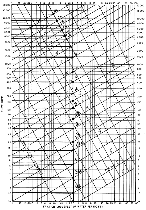
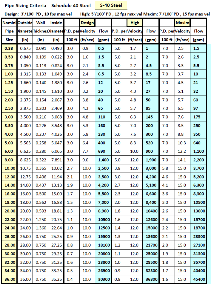
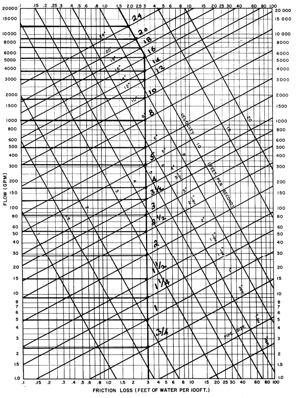
Design Criteria: 3' Frictional Pressure Drop per 100' Pipe Length with a Maximum Velocity of 10 ft/sec
Figure - 1 Friction Loss for CLOSED Piping Systems: Schedule 40 Steel Source: Carrier Systems Design
OPEN SYSTEMS
Design Criteria: 3' Frictional Pressure Drop per 100' Pipe Length with a Maximum Velocity of 10 ft/sec
Figure - 2 Friction Loss for OPEN Piping Systems: Schedule 40 Steel Source: Carrier Systems Design
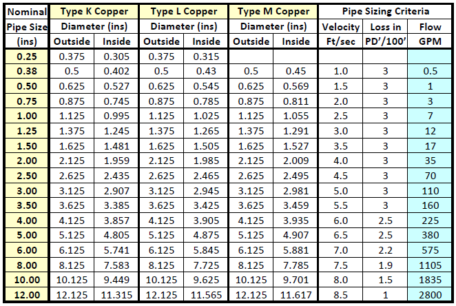
COPPER Physical Dimensions and Sizing Criteria (ASPE Data Book)
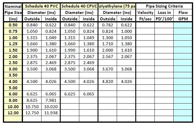
PLASTIC Physical Dimensions and Sizing Criteria (ASPE Data Book)
Copper Pipe Sizing Chart

Design Criteria: 3' Frictional Pressure Drop per 100' Pipe Length with a Maximum Velocity of 10 ft/sec
Figure - 3 Friction Loss for Copper Piping Systems: Types K, L, & M Source: Carrier Systems Design
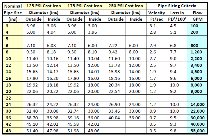
CAST IRON Physical Data Hydraulic Handbook Colt Industries
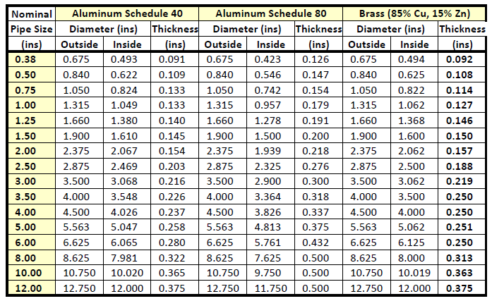
ALUMINUM , BRASS Handbook for Mechanical Engineers : Baumeister & Marks
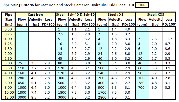
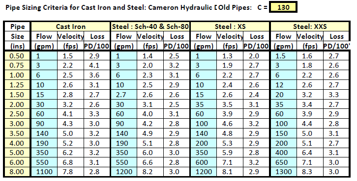
PIPE DESIGN BASED ON HAZEN WILLIAMS FORM(UfL=A0.2083 x (100/C)^1.85 x Q^1.85/D^4.8635 )
Source: Cameron Hydraulic Data, 1926-62

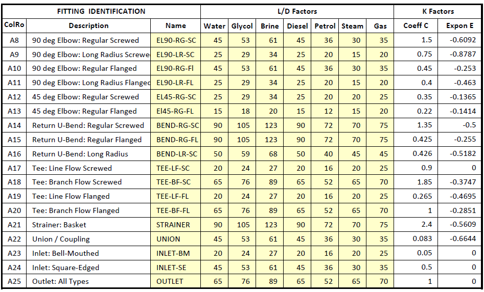
Dynamic Pressure Losses through Fittings
EL = L/D* D (EL = Equivalent Length. L=Pipe Length, D = Pipe Diameter)
Velocity Pressure Factor (K) forWater : K = C*D**E: Pressure Drop (PD) = K*VP
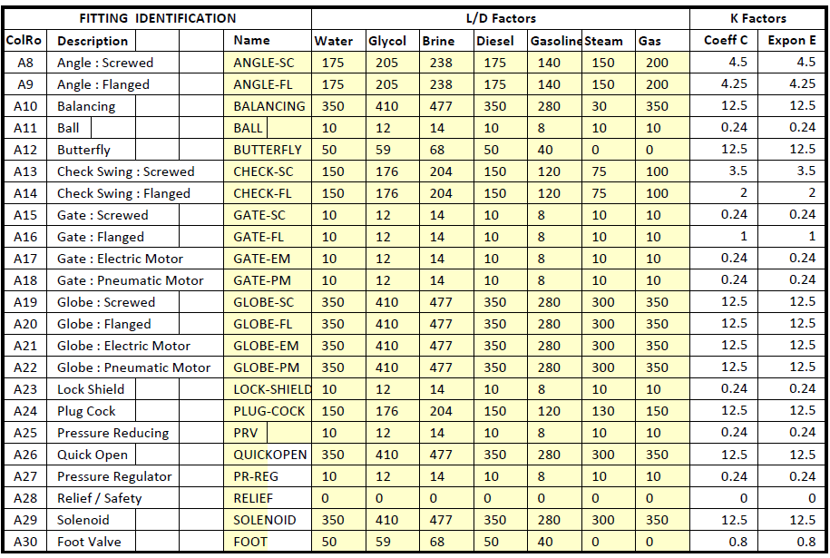
Dynamic Pressure Losses through Valves
EL = L/D* D (EL = Equivalent Length. L=Pipe Length, D = Pipe Diameter)
Velocity Pressure Factor (K) forWater : K = C*D**E: Pressure Drop (PD) = K*VP
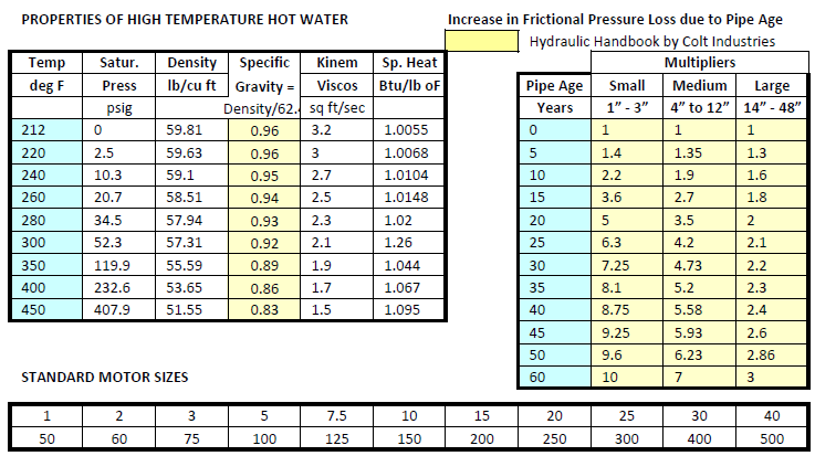
PROPERTIES OF LIQUIDS

STEAM PRESSURE CLASSIFICATION AND PIPE SIZING DESIGN CRITERIA

LOW PRESSURE STEAMPIPE SIZING CRITERIA : Flow Rates of Steam (lbs/hr)
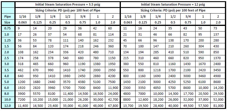
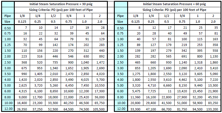
MEDIUM PRESSURE STEAM PIPE SIZING CRITERIA : Flow Rates of Steam (lbs/hr)
HIGH PRESSURE STEAMPIPE SIZING CRITERIA : Flow Rates of Steam (lbs/hr)
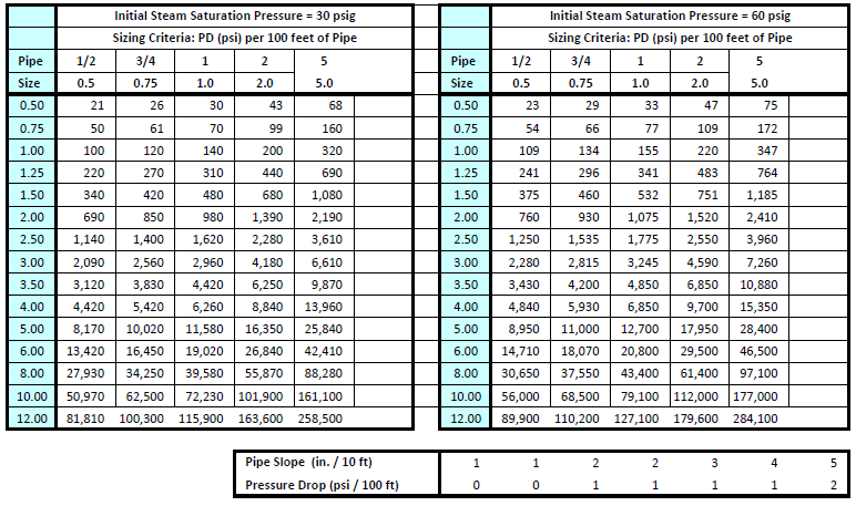
Pressure Drop (psi/100') sizing criteria for open gravity (sloped pipe) condensate return
CONDENSATE FLOWRATE (lbs/hr) Condensate Return Pressure = 0 psig
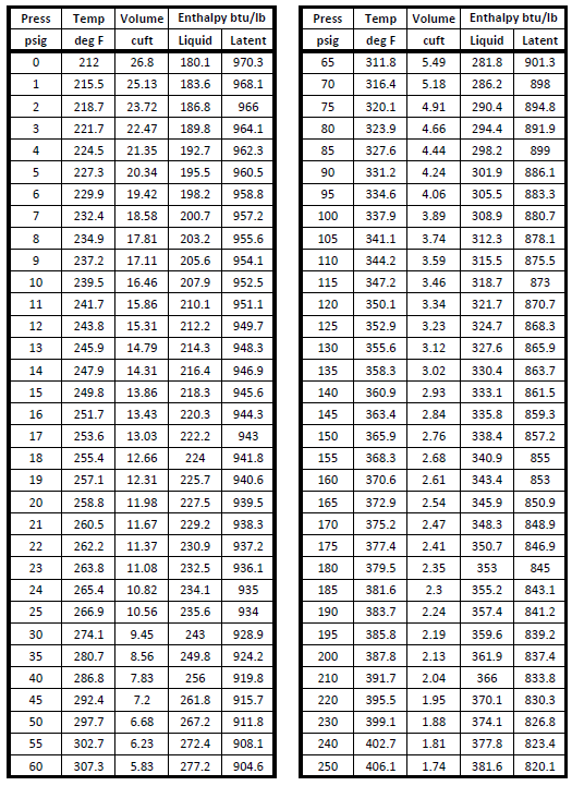
PROPERTIES OF STEAM
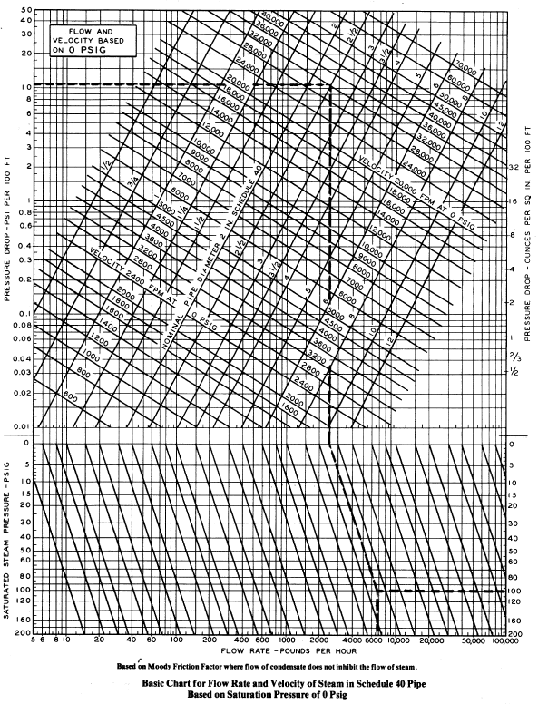
Example: 6800 lbs per hour of steam flow in a 2 1/2 inch pipe at 100 psig pressure.
What is the pressure (psi) drop per 100 ft length of pipe and the flow velocity?
Answer: psi/100' = 11 velocity = 32,000 fpm
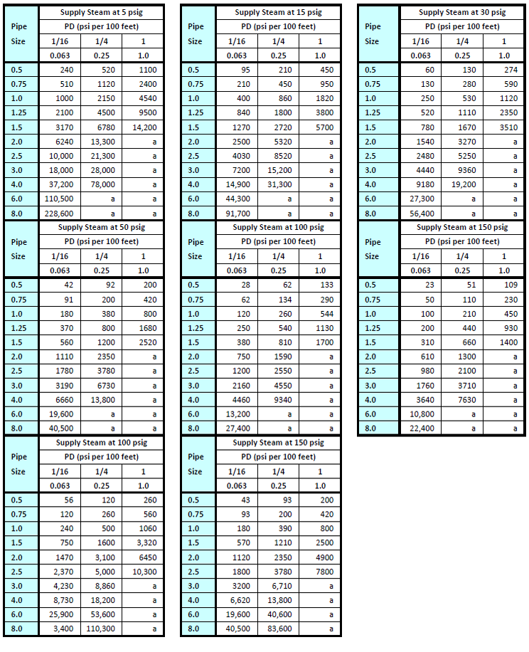
Figure - 17 Steam Flow Rates at Various Pressures and Velocities for Schedule 40 Pipe Source: ASHRAE
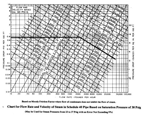
| Figure - 18 Steam flow at 30 psig Source: ASHRAE Design Criteria: 0.75 psi per 100 ft pipe Max Vel = 6,000 fpm |

| Figure - 19 Steam flow at 50 psig Source: ASHRAE Design Criteria: 1.0 psi per 100 ft pipe Max Vel = 8,000 fpm |

| Figure - 20 Steam flow at 100 psig Source: ASHRAE Design Criteria: 2.0 psi per 100 ft pipe Max Vel = 10,000 fpm |
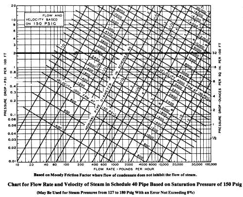
| Figure - 21 Steam flow at 150 psig Source: ASHRAE Design Criteria: 2.0 psi per 100 ft pipe Max Vel = 10,000 fpm |
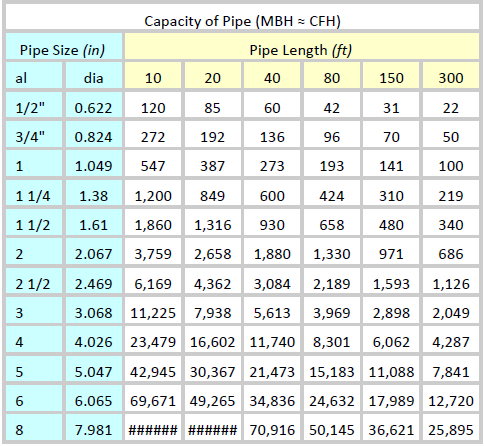
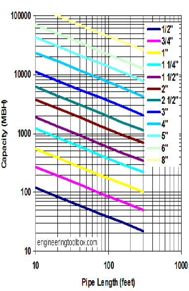
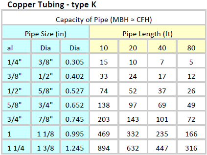
Natural Gas Pipe Sizing Tables and Charts
Steel Pipe - Schedule 40
Downstream Pressure

- inlet upstream pressure is more than 5 psig (35 kPa)
- fittings factor 1.2 - equivalent pipe length = pipe length + 20%
For natural gas the nominal BTU/cf varies from about 900 to 1100 BTU/cf. In general it is common to set
- 1 Cubic Foot (CF) = Approx 1,000 BTUs
- 1 CFH ≈ 1 MBH
- 1 Btu/h = 0.293 W
Steel Pipe - Schedule 40
- pressure less than 1 1/2 psig pressure drop 0.5 inches water column
- specific gravity of natural gas energy content in natural gas 10
- 1 Cubic Foot (CF) = Approx 1,000 BTUs 1 CFH = 1 MBH
- common to use fittings factor 1.5 - equivalent pipe length
in table above = pipe length + 50%
For natural gas the nominal BTU/cf varies from about
900 to 1100 BTU/cf. In general it is common to set
|
|
|
|
| |
The capacity of a low pressure natural gas (less than 1 psi) pipe line can be calculated with the Spitzglass formula like
q = 3550 k ( h / l SG)1/2 (1)
where
| q = natural gas flow capacity (cfh) | h = pressure drop (inWater Column) |
| l = length of pipe (ft) | k = [d5 /(1 + 3.6/d + 0.03 d)]1/2 |
| d = inside diameter pipe (in) | SG = specific gravity |
For natural gas the nominal BTU/cf varies from about 900 to 1100 BTU/cf . In general it is common to set
1 Cubic Foot (CF) = approx 1,000 BTUs
1 CFH = 1 MBH
The specific gravity of natural gas varies from 0.55 to 1.0 .
The downstream pressure in a houseline after the meter/regulator is in general in the
range of 7 to 11 inches Water Column, or about 1/4 psi.
Example - Natural Gas Pipe Capacity
The capacity of a 100 ft natural gas pipe with a nominal diameter 0.5 inches (actual ID 0.622 in )
and 0.5 inches WC pressure drop can be calculated as
k = [(0.622 in )5 /(1 + 3.6 / (0.622 in) + 0.03 (0.622 in))]0.117
q = 3550 0.117 ( (0.5 in) / (100 ft) 0.60 ) 1/2 = 37.9 cfh
Specific gravity of natural gas is set to 0.60.
Horizontal Fixture Branches and Stacks | Building Drains and Sewers |

|

|

ROOF DRAIN AND LEADER SIZING

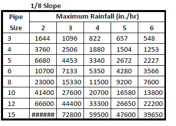
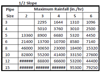
HORIZONTAL RAINWATER PIPE SIZING | HORIZONTAL RAINWATER PIPE SIZING |

|
HORIZONTAL RAINWATER PIPE SIZING
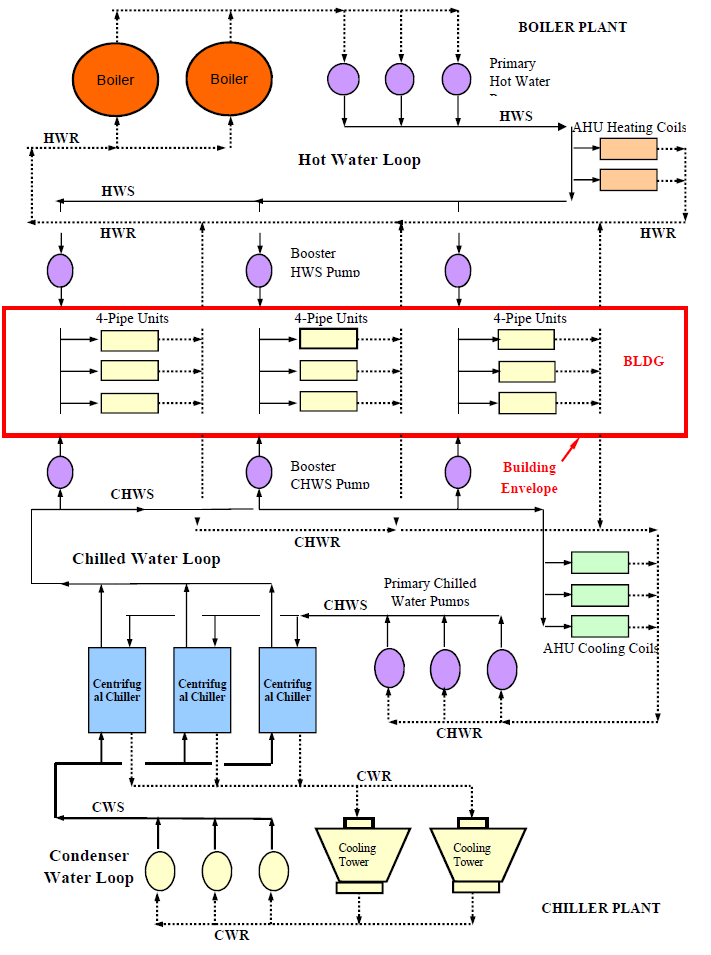
Example of Primary-Secondary Piping Network System