Heat Transfer
Three modes of heat transfer are;
- Conduction
- Convection
- Radiation
When two solids at different temperature are placed in thermal contact with each other, there is a flow of heat from the hotter solid to the colder solid until they reach equilibrium (Both at the same temperature).
| Hot 200oF | Cold 0oF |
Heat transfer: -The transfer of energy from a more excited group of molecules (higher temperature) to a less excited group of molecules (lower temperature).
Heat transfer is the transfer of energy between two regions due to a difference in temperature or heat flows down the gradient of temperature.
It is heat that is transferred not cold. If you sat on a block of ice, you feel cold because heat from you is being transferred to the ice until you and the ice reach the same temperature. The cold from the ice is not being transferred to you.
Steady State Heat Transfer
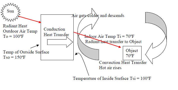
Conduction is the flow of heat through the substance due to a difference in temperature on two sides of the substance. Conduction is typically associated with the flow of heat through solids, but it can also happen through liquids and gases.
Convection is the heat transfer by mass motion of the substance. Convection therefore does not occur within a solid since it depends on the freedom of substance to move because of temperature difference. Convection is associated with fluids (liquids and gases).
Radiation is the heat transfer by electromagnetic radiant heat energy through space from one body to another without affecting the space in between.
Example of Radiation

Radiant heat transfer to a body and its surrounding temperature depends on the absorptivity (A), transmissivity (T), and reflectivity (R).

Surface temperature of (1) will be much higher because the black rough surface absorbs heat. Body (1) will transmit more heat because of its higher conductivity.
Surface temperature of (2) will be much colder than (1) because most of the radiant heat energy will be reflected. Plastic will not transmit heat as well as steel.
A + T + R = 1
A = absorptivity, T = transmissivity, R = reflectivity
| Summer Outdoor air temperature To = 100oF Surface temperature 150oF on June21, Latitude 20oF | Average indoor air temperature Ti= 75oF | Initial air temperature Ti = 70oF Final air temperature Ti = 80oF |
Heat Transfer through the solid building envelope is due to a difference in temperature on either side of the solid envelope.
QT = As * U * (To - Ti)
QT = conduction heat transfer through the envelope
As = surface area of building envelope
U = conduction property of building envelope material
Heat Gain by the air in the enclosed space is because heat is being added to it through the building envelope. This heat is absorbed by the mass of air in the space increasing it’s temperature
QH = Ma * Spht * (To - Ti)
QH = Room heat gain from envelope inside surfaces through convection
Ma = Mass of air (lbs)
Spht = Specific heat of air
Heat Transmission Through the structural element conduction

- Heat Transmission (Q) occurs down the gradient of temperature (from higher temperature to lower temperature). It is directly proportional to the temperature difference. Fluid flows down the gradient of pressure. Electrical current flows down the gradient of voltage.
Q ~ (T2 - T1); T2 > T1; greater the difference in temperature, greater the heat flow. - Heat Transmission (Q) is directly proportional to the surface area of the structural barrier (conducting element). The surface area can be different on each side of the structural barrier in which case use the average area of both sides. A= (A1+A2) / 2
Q ~ A; greater the surface area, greater the heat flow.
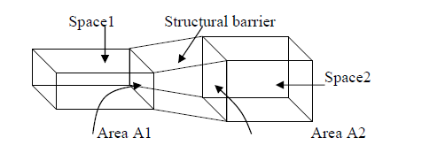
- Heat Transmission (Q) is resisted by structural barrier through which heat is being conditioned. Heat flow is inversely proportional to the resistance of the structural element.
Q ~ 1/R; greater the resistance, less the heat flows.
Heat Transmission Equation
Q ~ A * 1/R * (T2 - T1)
A = surface area of material
R = resistance of material
(T2 - T1) = difference in temperature on either side of material.
Materials conduct heat. The ability of different materials to conduct heat varies considerably. Best conductors are metals. Bad conductors are insulators-cork, felt, fiberglass, and Styrofoam.
Summary
Heat flows through structural barrier (wall), separating two spaces at different temperatures, depends on 3 factors;
- The surface area of the structural barrier (wall, roof, etc.). The greater the surface area, the greater the flow (directly proportional).
- The temperature difference on either side of the structure (or between the two spaces in winter). The greater the temperature difference, the greater the flow (directly proportional).
- Heat conduction properties of structural barrier or the Resistance (R) to heat flow offered by the building material. The greater the resistance, the less the heat flow (inversely proportional).
Conductivity (K)
The ability of a substance to transmit heat by conduction is a physical property of a particular material. It is called thermal conductivity. The symbol commonly used is "K".
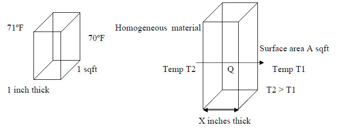
Definition (IP units)
Conductivity is the amount of heat in Btu flowing through a homogeneous material one inch thick, in one hour, through a surface area one sq.ft., when temperature difference on each side is one oF.
Heat transfer by conduction through a homogeneous material.

Q = heat transfer flow rate (Btuh or Btu/hour)
As = surface area (Sq.Ft.)
K = conductivity of building envelope material (Btu-inch per hour per sq.ft. per oF
X = homogeneous material thickness (inch)
T2 - T1 = temperature difference (oF)
Q (Btu/hour)= A(Sq.Ft.) * K/X(inch) * (T2 - T1) (oF)
K = Btu .Inch / Hour.Sq.Ft..oF (units of K)
The value of K is for one inch of a homogeneous material. Heat conductivity property of a homogeneous material for X inches is K/ X. Heat flow decreases with thickness
Example: Calculate overall heat loss through a brick wall. Wall thickness = 4"
Brick conductivity = 9.0 Btu .(inch)
Hour.Sq.Ft..oF
Wall dimension = 15' x 10'
Outside Surface temperature = 10oF. Inside Surface temperature = 70oF
| Q = A * | K | * (T2 - T1) | |
| X |
| = (15' x 10') * | 9.0 | * (70-10) = 20,250 Btu/Hr | |
| 4 |
Example: Heat (Q) flow through a wall is 230 Btu/Hr, when the outdoor air temperature is 105oF and indoor air temperature is 75oF. What is the Heat flow through the wall when the outdoor air temperature decrease to 95oF and indoor air temperature remains the same.
| Q = A * | K | * (T2 - T1) | |
| X |
| Q1 = A * | K | * (105 - 75) = 230 Btu/Hr | |
| X |
| Q2 = A * | K | * (95 -75) = Q | |
| X |
| Q1 | = | (105 - 75) | = | 230 |
| Q2 | (95 - 75) | Q |
| Q = 230 * | 20 | = 153.3 Btu/Hr | |
| 30 |
| Btu.(inch) | |
| Hour.Sq.Ft..oF |
What should the thickness of the wall be so that the heat loss does not exceed 43,750 Btu/Hr.
| 43,750 = 1,000 * | 5.0 | * (70 - 0) | |
| X |
| 5 | = | 43,750 | = 0.625 | |
| X | 1,000*70 |
| X = | 5 | = 8" | |
| 0.625 |
| Btu.(inch) | |
| Hour.Sq.Ft..oF |
For 2 inches of Insulation, the heat transfer rate is
| K/td> | = | 0.25 | = 0.125 | Btu |
| X | 2 | Hour.Sq.Ft..oF |
There are many building materials that are not homogeneous. Example, hollow concrete blocks can be 4 inch thick, 8 inch thick, 12 inch thick, and the hollow part may vary in thickness and may be filled-with air or with loose insulation. In this case the manufacturers of the building materials will provide an overall K/X value for the thickness of the composite material. This is called conductance (C).
Conductance (C) is the rate of heat flow in Btu flowing through a non-homogeneous material of a given thickness, in one hour, through a surface area one sq.ft., when temperature difference on each side is one oF.
Heat transfer by conductance through a non-homogeneous material
Q (Btu/hour)= A(Sq.Ft.) * C * (T2 - T1) (oF)
| C = | Btu | = Conductance (units of conductance) | |
| Hour.Sq.Ft..oF |
Example: Calculate winter heat loss through a hollow concrete brick wall 8 inch thick. Conductance of hollow concrete blocks = 9.0
| Btu.(inch) | |
| Hour.Sq.Ft..oF |
Wall dimension = 15' x 10'
Outdoor Surface temperature = 10oF
Indoor Surface temperature = 70oF
Q = A * C * (T2 - T1) = (15' x 10') * 9.0 * (70-10) = 8,100 Btu/Hr
Example: Heat (Q) flows through a wall of dimension = 20' x 10' is 3,600 Btu/Hr. The wall is made of 8"x 8"x16", 3 oval core concrete blocks.
Conductance of the concrete blocks is = 0.6| Btu.(inch) | |
| Hour.Sq.Ft..oF |
Q = A * C * (To - Ti)
Ti = Inside air (or wall surface) temperature = 80oF
A = 20' x 10' sqft ; Q = 3,600 btu/hr ; C = 0.6
To = Outside air (or wall surface) temperature = ?
3,600 = (20' x 10') * 0.6 * (To -80)
| To - 80 = | 3,600 | |
| (20*10)*0.6 |
To = 80 + 30 = 110oF
Example: The heat loss through a wall of dimensions = 25' x 10' is 8,750 Btu/Hr. Outdoor air and surface temperature = 20oF and indoor air and surface temperature = 70oF
What is the conductance of the wall material?
Q = A * C * (T2 - T1)
| C = | 8,750 | = | 8,750 | = 0.70 | Btu |
| (25x10)x(70-20) | 250x50 | Hour.Sq.Ft..oF |
Surface Air Film Conductance (f ).

The transfer of heat from air to a surface, and from surface to air is called surface conductance or film conductance or film coefficient. There is an air film next to surface that has the same effect as another building material with its own value of conductance and resisting heat flow through the structural (thermal) barrier.
Surface Conductance (f) is the amount of heat transfer in Btu from an inside surface to space air, or from outside air to an outside surface, per surface area of one sq.ft., when temperature difference on each side of the film is one oF.
Q = A * f * (T2 - T1)
Q= heat transfer flow rate (Btuh or Btu/hour) A = surface area
f = surface conductance of the air film (Btu per hour per sq.ft. peroF)
T2 - T1= temperature difference between surface and air (oF) , each side of the air film
A surface film cannot exist by itself. There has to be a solid surface for the film to cling to.
Typical values of Air Film Surface Conductance (f):
Inside surface still air f = 1.47 (resistance hsi = 1/1.47 = 0.68)
Outside surface @15mph wind velocity f = 5.9 (resistance hso = 1/5.9 = 0.17)
Air Space Conductance (Ca)
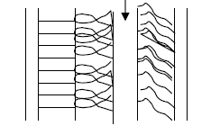
An air space layer sandwiched between two building materials that make up a structural (thermal) barrier (wall, roof), provides good inexpensive insulation. It is treated as a homogeneous material with a conductance value of its own. The conductance value is the same for all air layer thicknesses. Airspace conductance is the heat flow in Btu/hr flowing through a surface area one sq.ft of air space, when temperature difference on each bounding surface is one oF. Airspace conductance cannot exist by itself. It is part of a composite structural (thermal) barrier.
Air Space Layer (any thickness) Conductance = 1.0
Q = As * Ca * (T2 - T1)
As = Surface area of composite wall or roof
Ca= Airspace conductance of (Btu per hour per sq.ft. per oF)
T2 - T1= temperature difference (oF) between each side of air layer
Airspace conductance cannot exist by itself. It occurs as part of a composite structure
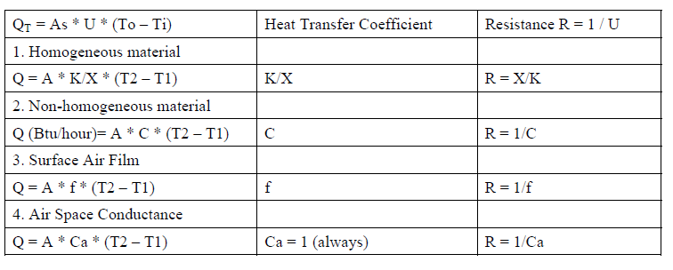
Overall Heat Transfer Coefficient
Equations 1- 4 are based on two temperatures T1 and T2 on each side of the layer. A composite structural (thermal) barrier is made of several layers, and each layer has its own temperatures on each side of it’s surface. The equation to calculate heat transfer across a composite structural (thermal) barrier is to treat the composite structural (thermal) barrier as a single material with a composite heat transfer coefficient (U).
QT = As * U * (T2 - T1)
QT = heat transfer through the composite structural (thermal) barrier (Btu/hr)
As = surface area of composite structural (thermal) barrier (Sq.Ft.)
| Btu.(inch) | |
| Hour.Sq.Ft..oF |
T2 = Outside temperature of composite structural (thermal) barrier (oF)
T1= Inside temperature of composite structural (thermal) barrier (oF)
Overall Heat Transfer Coefficient (U) is the heat flow in Btu/hr flowing through a composite structural thermal barrier (wall, floor or roof etc.) when temperature difference on each bounding surface is one ºF. The Overall heat transfer coefficient of a composite structural barrier is the reciprocal of the overall resistance of the barrier. This is done by adding the resistance of each layer of the composite wall or roof and taking the reciprocal.
The resistance of each layer material is the reciprocal of the heat transfer coefficient.
For a homogeneous layer of conductivity (K) and thickness (X), the resistance (R) = X / K
For a non-homogeneous layer of given thickness with conductance (C), the resistance (R) = 1 / C
For a surface film of conductance (f) the resistance (R) = 1 / f
For an air space of conductance (Ca) the resistance (R) = 1 / Ca = 1 (Ca = 1 for all thicknesses)
Overall Resistance (Ε R ) = R1 + R2 + ----- Rn
U = 1 / Ε R Q = As * U * (To -Ti)
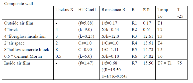
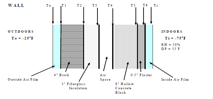
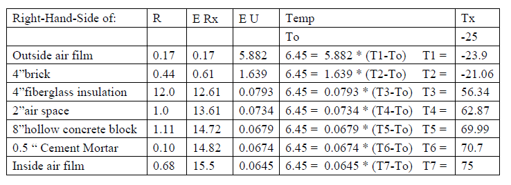
Example: Calculate the heat transfer through the wall (shown above) of dimension 100'L x 20'H when the inside temp is 79oF and outside temp is -30oF.
Q = A * U * (Ti - To). A = 100*20 = 2000 ft2, U = 0.0645, Ti - To = 70 - (-30) = 100
= 2000 * 0.0645 * 100 = 12,900 btu/hr.
Temperatures at the interfaces between layers.
The heat transferred from indoors to outdoors through each layer of the composite wall is the same. So the temperature at the interfaces can be calculated from Q = A * U * DT.
Q = 12,900 btu/hr, A = 2000 ft2, Q/A = 6.45 = Ε U * (Tx-To)
Consider the same wall in summer when the outside air conditions are DB = 105oF, RH = 50% and Dew Point DP = 83oF and the inside condition is 75oF. The temperature through the layers will decrease from 105oF (assuming no solar radiation heat and temperature build up on the outside surface of the wall) to 75oF. The moisture content W = 0.0246 and the DP = 83 will remain the same and the RH increases.
Q = A*U*(To-Ti) = 2000 * 0.0645 * (105 - 75) = 3870 btu/hr. Q/A = 1.935
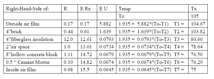
The side of the insulation towards the room is 80.6oF which is below the DP of 83oF. So condensation will start at some point within the insulation. A vapor barrier is required on the outdoor side of the insulation.

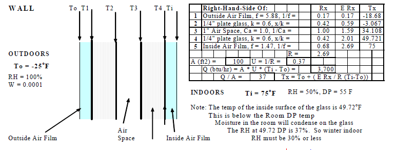

| T2 = To + | ∑Rx | * (Ti – To) = -25 * | 2.01 | * (75 - (-25)) = 49.72oF (below dew point temperature) |
| ∑R | 2.69 |
RH that gives a dew point temperature below 49.7oF (Dry bulb=75oF) = 37% (from psychrometric chart). So the indoor design RH for extreme outdoor winter climates (less than say -20oF) should not exceed 30%. For less extreme winter climates (from say 0oF to 20oF) the design indoor RH should be around 40%. Normal practice is to use a winter indoor design RH of 30% for all cold climates where the outdoor temperatures can drop below 32oF (freezing).
When the indoor RH is low (say below 20%) then it can affect people with respiratory problems and mild static electric sparks occur when a person enters the space from the outside cold and touches metal objects in the space. Low humidity also affects electronic equipment in operation (computer plotters, etc.) and silk clothes will cling to the body.
In summer the indoor design DB and RH can be allowed to drift upwards when outdoor air conditions exceed the design outdoor conditions. The building occupants can tolerate the less than comfort conditions for the few hours or days per year when such conditions occur.
In Minneapolis for example, the 99% design winter outdoor conditions might be -16oF, but extreme conditions of below -30oF can occur for a few hours or days during some years. The building occupants cannot tolerate the resulting indoor DB temperature conditions when this happens. So it is normal to add a safety factor to the winter heating loads or use -30oF or less in calculating winter heating loads. Another indirect safety factor that is used in determining winter design loads is not to take credit for solar heats gains and internal heat gains. The worst winter conditions usually occur at night when neither of these heat gains apply. Hospitals are exceptions.
In calculating winter energy loads credit must taken for solar and internal heat gains. Designers try to maximize solar heat gains in cold climates in order to save winter heating energy. The resulting increase in summer cooling energy can be minimized with shading devices for windows.
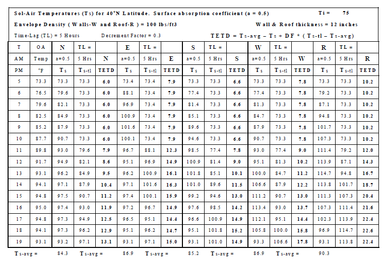
Sol-Air Temperature
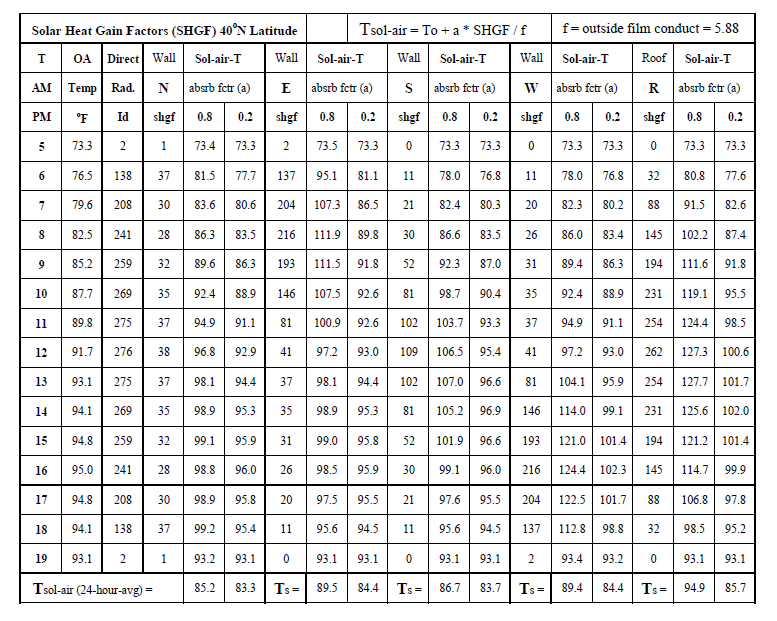
Sol-Air temperature concept is used to calculate heat transfer across a building envelope (walls and roofs) using the formula used in winter which does not account for the radiation heat gained by the outside surface of the wall. This simple heat transfer formula is Q = A * U * (To - Ti). However, in summer the solar radiation striking the outside surface increases the temperature of the surface. This temperature is called the sol-air temp or the equivalent outdoor air temp that can be substituted in the formula Q = A * U * (To - Ti) or Q/A = Ho * (Ts - To) where Ho is the outside surface air film coefficient and Ts is the outside surface temperature. Q (including the solar radiation impact) can be measured for a given A and so Ts can be calculated.
The table below shows how the solar radiation affects the sol-air temp. It depends on the radiation absorption properties of the outside surface. Black-colored, non-reflective materials have the highest absorption factors or coefficients and white reflective surfaces have the lowest coefficients. Ts = To + ( a * It / f ) + R where It is the total (direct and scattered / diffuse) radiation falling on the surface and R is a miscellaneous remainder/correction factor.
Total Equivalent Temperature Difference (TETD)
This method of calculating heat gains through walls and roofs is based on the sol-air temp concept and it takes into account the time lag due to the thickness and density of the wall or roof. After calculating TETD for a given envelope surface at a given hour, the heat gain through the wall or roof is Q = A * U * TETD where: TETD = Ts-avg - Ti + DF * ( Ts-tl - Ts-avg)
Ts-avg = 24 hour average sol-air temp for surface, Ts = sol-air temp at current hour
Ts-tl = sol-air temp at time-lag hours ago, Ti = Indoor temp, DF = decrement factor.

