MECHANICAL ENGINEERING DESIGN COMPUTER PROGRAMS FOR BUILDINGS
ABSTRACT
The mechanical engineering design computer programs described in this paper include loads, ducts, and pipes. The pipes program analyzez both HVAC and plumbing systems.All three programs are information-based in that the models of the building and mechanical systems can be developed with information available in user-definable (and user-expandable) data-base libraries. The hierarchical structure of the loads and ducts programs consists of terminals, rooms, zones, systems, plants, and buildings. This common structure enables the transfer of information between the programs. Room air quantifies from the loads program can be assigned to room terminal devices in the ducts program. Similarly, zone information can be transferred to fan-powered terminal boxes and system information can be transfered to aid-handling units. The ducts and pipes programs enable the simultaneous construction of both the engineering and graphical dimensional models. Three-dimensional graphical systems created by the ducts and pipes programs are made up of engineering elements linked to engineering data bases. The graphics modeling system functions incorporated into these two programs, such as copying, repeating, moving, scaling, rotating, and mirror-imaging, enable the engineer to develop the mechanical models quickly and efficiently. The models can be developed against the latest architectural and structural project drawings that are automatically loaded into background layers by an interdisciplinary project file management system.
INTRODUCTION
The need to develop HVAC design software modules as integrated components of a complete building development and operating system has been recognized by software professionals since the early years of software development in this industry(Daryanni 1970). Limitations in affordable computer hardware technology have, until recently, not only discouraged such integrated software development, but the scope of each program module was restricted to specific tasks, such as heating and cooling load calculations and duct sizing. Limitations in the utility software available in the past also affected the scope of building design software development. Without three-dimensional graphical systems to enter and edit data, and relational data bases to access engineering handbook and catalog data, the use of large and integrated mechanical engineering computer programs for buildings was difficult and impractical. Another limitation imposed on building services engineering (BSE) design software has been the traditional organization of this discipline, which consists of mechanical (HVAC and pipping), electrical (power and lighting), and piping (plumbing and fire protection). Software development has, until now, conformed to this organizational arrangement, although it originated before computers played any role in BSE design. These past limitations in computer hardware, utility software, and design team organization have, for example, resulted in the development of separate piping programs for different types of HVAC piping systems, such as chilled water and steam; different types of plumbing systems, such as domestic water and sanitary drainage; and other miscellaneous types of piping systems for buildings, such as sprinklers, natural gas, and medical gases. The three mechanical engineering program described in this paper are representative of the new generation of computer programs for the building industry that utilize all of the new and powerful hardware and software tools that became available to software developers only during the last three to five years. Some of the current features and future objectives of the program descrhibed in this paper are:
- Integration of mechanical engineering systems with systems in the other design disciplines and with third-party equipment selection programs.
- Engineering model construction with data bases that are internal and external to the programs.
- Three-dimensional graphical model construction of the physical mechanical engineering systems using architectural and structural background models.
- Simultaneous construction and linking of the engineering and graphical models;
- Input and output systems based on windows, shells, interactive graphics, menus, synonyms, commands, and user-defined command program files.
- Construction document development of drawings and schedules from schematic input models.
- Expanded scope of design and engineering analysis compared to versions of such programs previously available.
The systems described in this paper are based on current theory and technology available in building design and computer science. The net outcome of assembling and utilizing these technologies is a powerful, flexible, and efficient mechanical engineering design tool representing a significant step forward in the state of this art. The breakdown of BSE design software, until now, has been energy, loads, ducts, pipes, power, lights, equipment, and controls. The three mechanical engineering programs-loads, ducts, and pipes (SOM 1988a,b,1989)-described in this paper follow this traditional breakdown of software in the BSE design discipline. The programs were developed with and operate on a common platform that includes three-dimensional graphics; windows for multiple, simultaneous views of a graphical model; windows to enter, review, revise, and retrieve information from data bases; menus for easier interaction with the system; command for specific and global editing; user-defined synonyms for frequently used instructions; and user-created command program files to execute repeated groups of commands and to define repeated command logic sequence. Using these platform features, the engineer can access extensive engineering library data bases, which contain most of the information (from handbooks, catalogs, and other engineering reference sources) that is required for design. The data bases for building elements such as walls and roofs, design criteria, and standards are user accessible, definable, and expandable. Using the graphical features of the programs, the user can create double-line or single-line plan and elevation views and three-dimensional models of ducts, pipes, and equipment from schematic, single-line input models.
SYSTEMS INTEGRATION
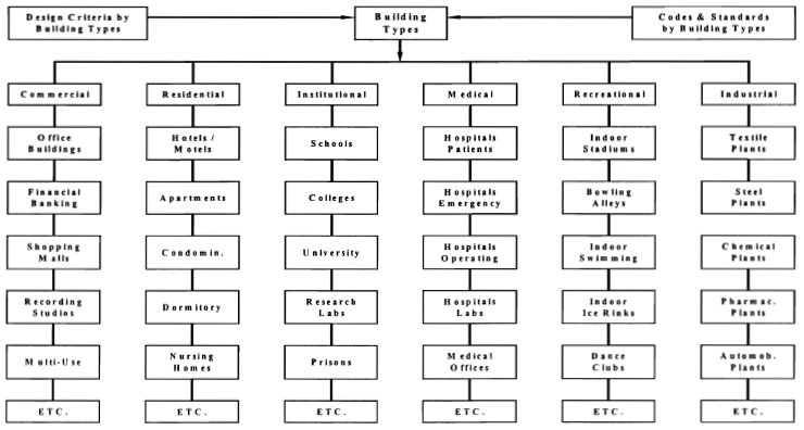
The three mechanical engineering programs described in this paper have been developed with the ultimate objective of achieving an integrated building development and operating system. To achieve such an objective, mechanical engineering systems must first be developed as integrated components of a BSE design system. A BSE design system is dependent on other design systems that include architecture and structural engineering. This is particularly true in space coordination, where three-dimensional graphical systems play an important role. The design system lays the ground-work for systems in the other segments of the building industry, which include financial planning and costing, equipment manufacturing, project construction, and operation/maintenance. Design systems must therefore be developed so that they can exchange information with systems in the other segments of the building industry. Although interaction occurs continously between the architectural and engineering disciplines during building design development, there is an even closer relationship between the mechanical and electrical engineering design processes. Figure 1a shows the loads, ducts and pipes programs as integral modules of the bigger BSE design system. The BSE design program modules are organized into the followeing categories (Thomas 1990):
- An "evaluation system" (energy, loads, and lights programs) to analyze the building environment and to determine how to maintain the required building conditions. These three programs share the same client criteria and architectural input requirements.
- An "equipment (selection) system" (lights and equipment programs) to treat the building environment and to maintain the required conditions. These programs are typically supplied by the manufacturers of the equipment.
- A "distribution system" (ducts, pipes, and power programs) to move energy and fluids (in various forms) from a generating source to the equipment system. These three programs share the same subroutines for network and circuit analysis, searching, sorting, convergence, etc.
- An "operation (equipment and controls) system" to make the total dynamic BSE design system work the way it should. These programs are typically part of building management (automation/control) systems. However, their operating criteria requirements are determined by the first three design systems.
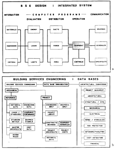
Figure 1 Building services engineering design programs and data bases
With building systems integration as a major objective, the loads, ducts, and pipes programs have been developed so that they can be interfaced with equipment performance data bases and selection programs offered by equipment manufacturers. The programs are organized so that there are clear, well-defined, and distinct interfaces separating the design functions from the equipment-related functions. Figure 2a shows the organization of the ducts program, which can automatically select equipment and schedule its performance by accessing and executing third-party equipment data bases and selection programs. In order to produce a continuous, uninterrupted, computed design process, two levels of interface must be defined between the design and equipment modules. They are design-to-equipment and equipment-to-design, as shown in Figure 2b. The design program generates the input required by the equipment selection program and the output from the selection program must be returned to design so that it can be edited and scheduled. Figures 3a and 3b show the design discipline, of which BSE design is a subcomponent, as part of the bigger picture of building development and operation (Thomas 1990). Information flow from the building design team to the building operations teams is presently a one-way process. Information from building management (computer-based) systems must be statistically analyzed, screened, converted into a standard format, and returned to the design systems through historical data bases.

|

|
Figure 2 Equipment performance catalogs, selection, and schedules. |
Figure 3 Systems integration across the building industry |
ENGINEERING MODEL CONSTRUCTION WITH DATA BASES
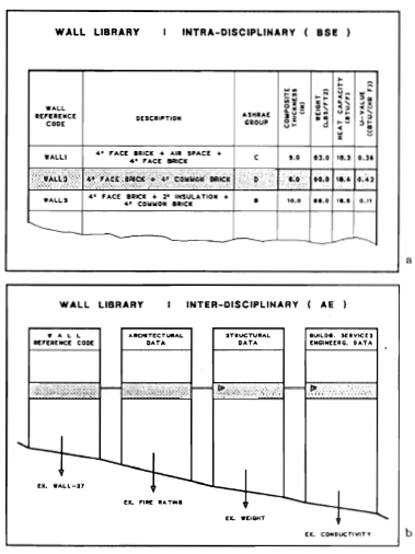
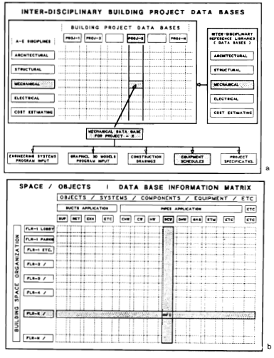
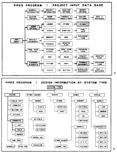
Computer hardware technology to store and transfer information, and software technology to access, review, and analyze information have made significant advances in recent years. The loads, ducts, and pipes programs utilize this technology extensively and have been developed on a large and comprehensive data-base system. The organization of an unduplicated information system of data bases that is common to, and easily accessible by, all the BSE program module plays an important part in integrating these modules. The information required by the loads, ducts, and pipes programs is organized into reference libraries and project libraries, as shown in Figure 1b (Thomas 1990). Reference library information is for the use of all projects. Project library information is specific to the project, and it can be developed by customizing reference library information. Project information that can potentially be used by future similar projects can an should be copied back into the reference library. Figure 5a shows the organization of reference and project libraries for the loads program. The user can increase the power and usefulness of the programs by expending the reference libraries. Figure 6a shows the mechanical project data base as an integral part of an architectural-engineering design data base using integrated reference libraries. Figure 6b shows BSE project graphical and text data bases organized by space (architectural and structural models) and system (mechanical models). Using an interactive information management systems, the program user can request reports and drawings (plans and elevations) about a complete mechanical system, which can occupy several floors; by floor, which can include all the mechanical systems on the floor; or by system segments on a selected floor Figures 5a, 7a, and 8a show the organization of project input data bases of the loads, ducts, and pipes programs. Each input field is backed up by a default value and minimum-maximum range. The default value can be overridden by an input value, a master value, or a library value. The default and range values are also functions of system type (Figure 7b and 8b) in the case of the ducts and pipes programs and building, space, or building element type (Figure 5b) in the case of loads program. Note that is possible to set up several alternative library data bases to the programs' default data bases, as shown in Figure 5b.
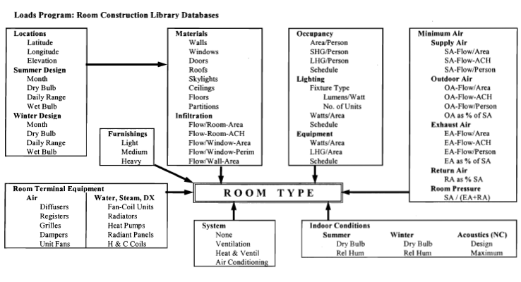
Figure 9a shows the organization of the room reference library data base in the loads program. The user can expand and refine this data base for different types of building and rooms. The library can be user to set up standards for indoor air conditions, ventilation, occupancy, lighting, and equipment. The other building element libraries, such as those for walls and roofs, are organized like the room library so that the user can expand the libraries and set up office standards. Figure 9b shows the construction of a room within a building using reference library data bases. The libraries on the outside for building materials, grazing, profiles, and criteria are project independent. The libraries on the inside windows, doors, skylights, and occupancy are project dependent and are developed with the help of reference libraries. For example, a project windows data base record requires the geometry of the windows besides grazing properties. The engineering libraries used by the programs include tables, equations, and information from the following sources:
Loads Program: Cooling and Heating Load Calculation Manual (ASHRAE 1979), ASHRAE Handbook - 1989 Fundamentals (ASHRAE 1989), and DOE 2.1C Reference Manual (U.S. Departament of Energy 1984).
Duct program: ASHRAE Handbook - 1989 Fundamentals (ASHRAE 1989), HVAC Systems - Duct Design (SMACNA 1981), and Duct Construction Standards(SMACNA 1985).
Pipes Program: ASHRAE Handbook - 1989 Fundamentals (ASHRAE 1989), Fundamentals of Plumbing Design (ASPE 1983), BOCA National Plumbing COde (BOCA 1989), and the Engineering Data Book (Hydraulic Institute 1979).
|

|
| Figure 8 Pipes program-input and systems design criteria data bases. | Figure 9 Loads program-room construction using data bases |
GRAPHICAL MODEL CONSTRUCTION
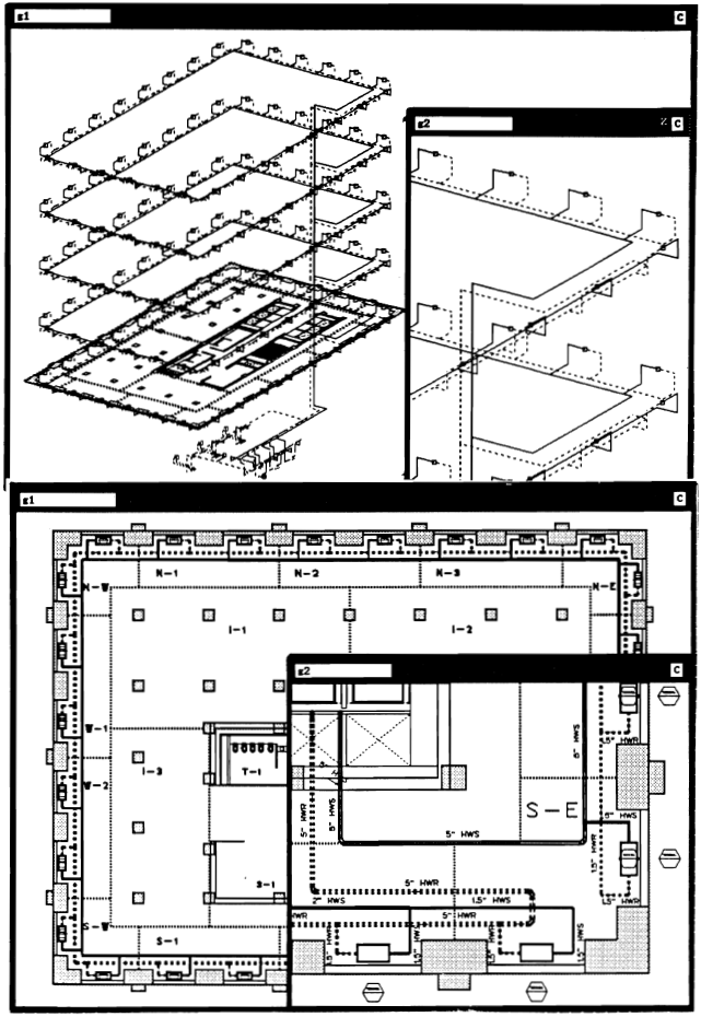
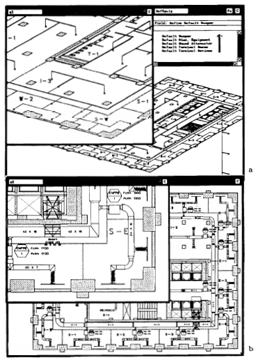
BSE design using the loads, ducts, and pipes programs consists of full-scale graphical model construction using actual engineering and building elements such as pipes and chillers. The elements of the graphical model are linked to its associated information in the data bases. The BSE model are developed against background of architectural and structural models, as shown in Figures 10 and 11. Analysis consists of simulating operating conditions. BSE design today, therefore, consists mainly of model construction and simulation, which is in contrast to designing and dragting in the recent past. Figure 12a shows model construction for a chiller plant. The chilled-water and condenser-water piping systems, including associated pumps and piping specialties, were developed in separate layers and save in different files. However, both systems enter and leave the same chiller equipment. Special features in the pipes program allow the user to orient equipment correctly relative to the piping system and pipe branch connections. Attributes linked to equipment elements include dimensions and library symbols. The program scales the symbols to fit the specified equipment dimensions. Figure 12a shows two open graphical windows being used to construct the graphical model and data being linked to a pump element using two input form windows. Figure 12b shows plan and elevation views generated by the pipes program. The program also generates several engineering reports regarding the piping system. The ducts shown in Figure 12b are in a separate layer and were generated separately by the ducts program. Figure 10a shows the construction of a reverse-return piping system serving terminal units at each windows of each typical floor with a direct-return system between the floors. The graphical modeling system features of copying repeating, moving, sealing, rotating, and mirror-imaging enable the design engineer to construct this model quickly and efficiently. Model construction begins by locating one terminal unit, adding the supply and return branch pipes from the floor below to this unit, copying and repeating (one command) this module for the other windows on this exposure to obtain the adjacent exposure, and using a mirror-imaging command to obtain the terminal unit with branch pipes for the opposite-side exposure. The main supply and return pipes are the added to complete the piping system on this typical floor. Copying and repeating(one command) the typical floor produces the piping system for the other floors. Finally, the main supply and return (vertical, riser) pipes are connected to each floor branch and the chiller room branch pipes. Figures 10b shows a typical floor-plan view of the piping system after program analysis. The floor plan was created with one command to analyze the input model and two command to create the plan view file and to load this file into a separate layer. Figure 11a shows the single-line schematic input of the duct system serving typical floors and Figure 11b shows the double-line plan view output generated by the program. This graphical output includes the duct sizes (text) and graphical representations of flexible ducts, terminal boxes, and other ductwork elements. Figures 13a and 13b are three-dimensional models of the ductwork and piping systems generated by the programs from schematic input models.
INPUT/OUTPUT (I/O)
The I/O system for the ducts and pipes programs enable the simultaneous construction of both graphical and engineering models. Graphical elements are linked to engineering text information during the schematic input model construction. The graphical output options include three-dimensional single-line; plan and elevation views, which may be single-line or double-line; and three-dimensional models. Several views of the graphical model can be displayed in multiple windows, which makes the task of input model construction easier (see Figure 12a). The view can be set as axonometric, orthographic, perspective, or plan with options to also set the angle, distance, elevation, gradient, eye-point, object-point, etc; The text information for project and reference data bases for all three programs can be entered and verified with "pop-up" data forms. Text data entries are checked against current library minimum and maximum limits. Default values are assumed if an entry falls outside these limits and also in the case of noncritical errors. A warning message is displayed where this occurs. The default levels are override-input, and reference library values. The override-input level is used to describe a specific item such as equipment. If this entry is omitted or if it falls outside the pre-defined limits, then the master-input value that applies to the typical item or most such items is used. If the master-input value is omitted, then the reference library value is assumed. The text data forms can also be considered as windows along with the graphical windows. You can open, close, resize, and reposition windows on the screen. You can also overlay one window over another when viewing large counts of project data. You can easily move back and forth between many groups of project data just by changing your current window. Windows are also the means for displaying the on-line help information and for entering commands to accomplish various tasks. Commands are used to open data forms direct an activity, add or edit libraries, and make global revisions. Menus provide a method of displaying selected data forms on the screen, allowing one to enter project information in orderly manner. Menus can also be used to bring up data forms and to build commands. User-defined synonyms can be used for frequently used commands. Groups of command can be organized as a program with interactive user interfaces and logical execution flow command sequences. Following the analysis, the programs produce a variety of engineering reports regarding building space and the mechanical systems. The loads program reports include summary and detailed reports of each room, zone, system, and plant and weather data. The ducts program reports include physical data; pressure, thermal, and acoustic conditions of each duct section and circuit; critical pressure, thermal, and acoustic circuits; fan, fittings, and equipment data; and detailed material estimates. The pipes program reports include physical data, pressure and thermal conditions of each pipe section and circuit, critical pressure and thermal circuits, primary and secondary pumps, fitting, equipment, and detailed material estimates.
LOADS PROGRAM
Loads program calculation methodologies are described in the Cooling and Heating Load Calculation Manual(ASHRAE 1979). They include weather data and weather profile projection routines; solar data calculations; psychrometrics; cooling load temperature differentials (CLTD) for external cooling loads such as roofs and walls; CLTD and cooling load factors(CLF) for windows and skylights; CLF for internal cooling loads from people, lights, and equipment; infiltration and ventilation cooling loads; and heating loads from conduction, infiltration, and ventilation. The data-base library system, organized as reference and project libraries, includes information on building elements, weather, design criteria, ventilation standards, operating profiles, lighting, equipment, and occupancy. Building element libraries include walls, roofs, floors, ceiling, partitions, and rooms. The weather data base consists of the summer and winter design conditions for all the major locations in the United States from ASHRAE (1989). Other locations can be easily be added to the library. The program will approximate the hourly weather conditions for typical days of the month using equations and tables. Alternatively, the user can enter project weather data directly into the project data base. The reference library also includes lighting, occupancy, equipment, operation and other buildig-related progiles from DOE 2.1C program (U.S. Department of Energy 1984). Architectural, structural, and other building-design-related drawings developed by CADD systems can be loaded into background layers of the loads program, enabling the direct measurement of distances and areas for input to the loads program. The hierarchical organizational structure of the loads program for building thermal analysis consists of rooms, zones, systems, and plants, as shows in Figure 14a. Room level information from the loads program can be automatically transferred to corresponding rooms with the same identification in the ducts program and assigned to terminal in the air distribution model on a percentage basis. Systems analysis consists of psychrometrically analyzing the thermal and flow conditions at all the critical points of the airflow paths in the system circuit, as shown in Figure 14B. The analysis begins at the leaving side or the cooling of heating coil of the air-handling unit and continues through the supply ducts; zones (terminal boxes); rooms; return plenums, ducts, and fans; outdoor an spill air ducts; and the supply fan unit. Supply fan arrangement can be draw-through or blow-through. Analysis is for a 24-hour period for typical days of each month for constant and variable-air-volume systems. The 24-hour weather for a typical day of each month can be entered through input forms, or the program will estimate these values using summer and winter design month and day, design temperatures, design hours, and daily range. The program calculates the simultaneous peaks of rooms, zones, systems, and plants. The system level report includes winter outdoor air humidification load, percent outdoor air on the basis of outdoor air requirements of all rooms in the system, percent spill air, and coil entering and leaving conditions.

|
| Figure 14 Loads program - thermal model structure and systems analysis. |
DUCTS PROGRAM
Ducts program capabilities enable graphical model construction, to full scale, of a complete air distribution system using engineering elements such as duct fittings, fans, boxes, terminals, sound attenuators, and dampers. Schematic input model construction is single-line for ducts with nodal points to represent the other engineering elements such as equipment and fittings. The engineering elements are linked to their physical, engineering, and other attributes in data bases during model construction. In the case of equipment, the attributes include dimensions so that symbols representing the equipment can be scaled to fit the dimensions in the output models. In the case of all other elements, the dimensions, three-dimensional configuration, and section and circuit identification and organization are all determined by the program from the schematic input model. Engineering reference libraries provide the physical, thermal, and acoustical properties of various types of air distribution equipment and materials. Duct materials include galvanized steel, stainless steel, uncoated steel, fibrous glass board, and various types of flexible ducts. Duct shapes include round, rectangular, and oval. All the major fittings in the HVAC Systems Duct Design Manual (SMACNA 1981) with their performance characteristics are included in the fittings library. Lining and insulation types are based on materials densities, and thicknesses. Equipment information is entered into the project data bases using input forms. However, the program is organized so that is can, in the future, be interfaced with equipment performance data bases and selection programs supplied by manufacturers. Sizing method options include equal friction, static regain, total pressure, velocity reduction, and constant velocity, and, for existing systems, there is also a presized option. Override conditions of friction loss per unit length, velocity and duct dimensions can be set for any section. Ductwork upstream and downstream of terminal boxes can be analyzed with different sizing methods. For example, high-velocity, static regain sizing for ducts upstream of terminal boxes; low-velocity, equal friction sizing for ducts downstream of boxes; and constant velocity for flexible ducts. The presized option can be used to evaluate revisions to existing systems as in the case of tenant redesign. Initial circuit pressure analysis is based on sizing criteria. The program calculates the loss through each circuit and determines the critical circuit. There are two circuit-balancing options. With the first option, the duct section sections in the noncritical circuits are iteratively reduced in size, within the design criteria limits, until the losses through these circuits are close to the losses through the critical circuit. This minimizes the balancing requirements of circuits. The second option iteratively increases the size of sections in the critical circuits, within size and clearance limits, until the critical circuit loss reaches a user-defined maximum limit. This is useful in the case of existing packaged air-conditioning units, where the existing available fan pressure cannot be exceeded. The thermal analysis option calculated the temperatures in the duct system due to transmission heat gains and losses. It begins with the coil leaving temperature of the system, calculates the temperature of the first section by adding the motor heat gain for draw-through systems, calculates the entering and leaving temperatures of each duct section, and determines the supply discharge air temperature at each terminal device of each room in the building. The supply and room air temperatures are compared in to the values used by the the loads program so that the system can be reanalyzed. There are two options for thermal reanalysis. The first option recalculates the supply air quantities at each terminal device in order to satisfy the design cooling and heating loads in each room. The program will then resize the duct system for the new air quantities or reanalyze the system for pressures using the existing duct sizes. The second option maintains the calculated duct sizes and recalculates the coil leaving temperature by an amount equal to the temperature difference in the circuit, with the maximum temperature rise for cooling systems or temperature drop in the case of heating system. The program will then recalculate the supply air quantities for all the other terminal devices (circuits) in order to satisfy design cooling or heating loads for each room. Acoustic analysis consists of calculating fan noise levels, attenuation within the ductwork system, and sound attenuator, selection requirements. Attenuator requirements are based on calculated noise levels at terminal devices and user-defined room noise criteria. Sound attenuators can be located in any section of the duct network. Acoustic data bases and analytical procedures are based on tables and equations in the HVAC Systems Duct Design Manual (SMACNA 1981). Duct construction analysis and material estimation are based on the Duct Construction Standard Manual (SMACNA 1981). The program calculates the dimensions, lengths, surface areas, and weights of ducts, insulation, and lining of each duct section. The program also summarizes these quantities for the entire system by material types. In the case of sheet metal ducts, the program determines the gage, rigidity class and reinforcement space of each duct section. The material estimation report also includes equipment quantities.
PIPES PROGRAM
The pipes program's graphical and engineering model construction procedure is very similar to that of the ducts programs. The program can be used to design HVAC and plumbing systems. Piping systems may be open (affected by atmospheric pressure) or closed (pressurized), as shown in Figure 15a. Open Systems include storm, sanitary, sanitary vent, condenser or cooling tower water, and steam condensate. Closed systems included chilled water, heating hot water, high-temperature hot water, domestic hot and cold water, brines and glycols at different concentrations, gases at different specific gravities, steam at different pressures, and different types of gasolines and fuel oils. Piping network layout options include two-, three-, and four-pipe systems, direct and reverse, return flow, and primary-secondary pumping systems. Primary pumps may be arranged in parallel and/or in series. Secondary circuits are automatically created and recognized by the program by the location of booster pumps in the graphical model network (see Figure 15b). Other piping system equipment that can be included in the model are primary equipment, terminal units, pressurization tanks, and various types of valves.

|
| Figure 15 Pipes program - types of systems, networks, and circuits. |
The pipes program makes extensive use of engineering and design criteria library data bases. The following are some of the libraries used by the program in analyzing the various types of systems.
Properties of fluids: Fluid types include water, brine, glycol, steam, gasolines, diesel oils, and fuel gases. Properties include kinematic viscosities, densities, and specific heats at different temperatures. Properties of pipe materials: Pipe materials include schedule 40, schedule 80, standard weight, and extra strength seel; different types of cast iron; copper types K, L, and M; and schedule 40 PVC and CPVC plastic. Properties include inner and outer diameters of standard sizes, densities, thermal conductivities, roughness factors, and corection factors for age. Properties of pipe insulation: Insulation materials include fibrous glass, urethane, elastomerics, phenolic foams, calcium silicate, and magnesia. Properties include densities and thermal conductivities at different temperatures. Pipe fitting and valves: Engineering performance data consist of K and L/D values for different diameters and velocities for different types of fluids and pipe materials. HVAC design criteria: The library includes sizing criteria, such as maximum velocity, pressure loss per unit length, and maximum flor for different types of fluids, pipe materials, nominal pipe sizes, and applications. One can set flags in cross-referencing matrix data bases to enure that the appropriate pipe material and insulation are used with different types of fluids and applications. Plumbing design criteria: This library includes sizing tables for analyzing roof drains and leaders, horizontal rainwater pipes, building drains and sewers, horizontal fixture branches and stacks, and horizontal and vertical vents. Pump performance data: These data are used for preliminary pump and motor sizing. The information includes pressure head vs. flow for different types and sizes of pumps for a given impeller diameter and rpm. The program uses pump laws to obtain operating condition for other impeller diameters and rpm's and for combinations of pumps in series and parallel.
Pipe sizing is based on criteria in the data bases or override input data. Pressure and circuit analysis, thermal analysis, and circuit-balancing procedures are similar to those of the ducts program, and some of the subroutines are common to both programs. Steam-sizing analysis is based on the general energy equations, since changes in temperatures, pressures, and fluid conditions have to be considered simultaneously. Steam condensate systems may be wet or dry, open or closed, and the sizing methods are based on ASHRAE Fundamentals (ASHRAE 1989). Gas pipe sizing methods are based on the ASPE Data Book (ASPE 1983). The program analyzes the primary pumping circuit and booster secondary pumping circuits. It determines the pump heads for open and closed systems and the pump performance circuits for pumps in parallel and/or in services. It also determines the system curves. Pressurization tanks may be open or closed, regular or diaphragm. Closed tanks may be located on the discharge or suction side of the pump or at the top of the piping system. Pressure heads are determined by the geometry of the graphical model.. Plumbing storm and sanitary drainage analyses are described in the ASPE Data Book (ASPE 1983), chapters 1 and 2. Tables from the ASPE Data Book used by the program are for building drains and sewers, horizontal fixture branches and stacks, gutter sizing, roof drain and leader sizing, and horizontal rainwater pipe sizing. Horizontal and vertical vent sizing is based on tables from the BOCA National Plumbing Code (BOCA 1987).
CONCLUSIONS
Computer hardware and data communication have advanced much more rapidly that software technology in recent years in the building industry. With today's hardware, it is not only possible to develop building design software that is integrated across the architectural-engineering design disciplines, but it is also possible to communicate the information generated by such design software directly to software systems in the other segments of the building industry. Systems integration is a very effective method of increasing the efficiency of the BSE design precess. Systems integration across architectural, structural, mechanical, and electrical design disciplines will increase the efficiency of the entire design process. For example, reference library information records for building elements such as walls, roofs, and floors should extend across the design disciplines with common identification numbers. Similarly, systems integration across the building industry segments of finance, design, manufacturing, construction, and operation will increase the efficiency of the entire building development and operation cycle. For example, it should be possible to communicate the electronic drawings, schedules, and specifications generated by the computer design systems to the other segments of the industry as electronic data and not on paper.
REFERENCES
ASHRAE. 1979. Cooling and heating load calculation manual. Atlanta: American Society of Heating, Refrigerating, and Air-Conditioning Engineers, Inc. ASHRAE 1989. ASHRAE handbook - 1989 fundamentals, chapters 23-27, 31-33. Atlanta: American Society of Heating, Refrigerating, and Air-Conditioning Engineers, Inc. ASPE 1983. ASPE data book, 1983-1984, volume 1-fundamentals of plumbing design. Sherman Oaks, CA: American Society of Plumbing Engineers. BOCA 1987. The BOCA national plumbing code/1987. Country Club Hills, IL: Building Officials & Code Administrators International. Daryanani, S. 1970. "Computers and the building industry. Use of computers for environmental engineering related to buildings." Proceedings of a symposium sponsored by NBS and ASHRAE, pp. 787-791. Hydraulic Institute. 1979. Hydraulic institute engineering data book. Cleveland, OH: Hydraulic Institute. SOM (Skidmore, Owings & Merrill). 1988a. HVAC application: Loads reference guide. IBM Architecture & Engineering Series. New York: International Business Machine Corp. SOM (Skidmore, Owings & Merrill). 1988b. HVAC application: Ducts reference guide. IBM Architecture & Engineering Series. New York: International Business Machine Corp. SOM (Skidmore, Owings & Merrill). 1989. Piping application: Pipes reference guide. IBM Architecture & Engineering Series. New York: International Business Machine Corp. SMACNA. 1981. HVAC systems duct design. Vienna, VA: Sheet Metal and Air-Conditioning Contractors' National Association, Inc. SMACNA. 1985. Duct construction standards. Vienna, VA: Sheet Metal and Air-Conditioning Contractors' National Association Inc. Thomas, V.C. 1990. "Intelligent computer programs for building services engineering design." ASHRAE Transactions, Vol. 96, Part2. U.S. Department of Energy, 1984. DOE-2, reference manual, version 2.1C. Berkeley, CA: Lawrence Berkeley Laboratory.
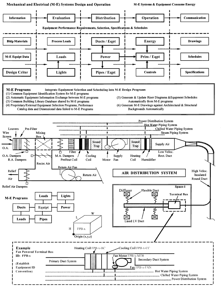
OBJECTIVES (Developing integrated M-E design computer programs)
The proposed project will investigate the economic of automating the present fragmented and intermittent information exchange process. M-E program development objectives will include:
Developing an integrated set M-E design program modules that use predefined project databases and other methods to exchange and update information between the various programs.
Interfacing proprietary equipment selection programs with the M-E design programs and generating drawings, schedules and specifications from the programs.
Defining program modules that can operate as a whole and also be able to operate independently in fragments to allow for flexibility and on-going manual review.
The project will investigate developing the following A-e supporting systems:
Standardized Building Description Language vocabulary, syntax & rules for A-E programs.
Standard Equipment Identification and Scheduling System for M-E and A-E design.
Automatic equipment and other data information exchange formats between M-E programs.
Common building library database shared by M-E programs and also A-E design programs.
Equipment performance & selection programs, and dimensional data linked to M-E Programs.
Generate & update Riser Diagrams, Schematics & Schedules from M-E design programs.
Generate M-E Drawings against Architectural & Structural background from M-E programs.
This type of M-E design software development team will require the support of, frequent interaction with, and progress review by:
M-E and A-E design firms such as Skidmore, Owings & Merrill M-E equipment manufacturers such as Carrier, Trane, York, McQuay and Bell & Gossett CAD firms such as AutoCAD and Betley Computational Fluid Dynamic (CFD) firms such as Fluent and Flovent Academic, Research and Software development groups
The main products resulting from this research will be educational material that use case studies of building projects that present a holistic, inter-professional, inter-disciplinary, object-oriented approach to the building sciences. Deliverable products will consist of:
Documentation of the M-E systems component of the communication and coordination life-cycle process model for different types and sizes of building projects.
Educational materials for universities that show M-E design as integrated system and as part of an interdisciplinary interactive process of A-E design - the way it occurs in practice.
M-E Design Software that integrates the design process

Integrated Ductwork Design and Equipment Selection

Building Databases Library Organization M-E Design Criteria
