Piping Design Program
Piping Systems and Networks
Piping systems can be open or closed. An open system is affected by atmospheric pressure. The flow in open condensate return and plumbing drainage systems is gravitational. The flow in an open cooling tower water system is forced. The pipe sections of an open network system are either all supply or all return. A closed network system includes both supply and return sections. A closed network system begins with a first supply section and ends with a last return section.
Open Network Systems
Pumps and static heads are used to force circulation in Open Systems except as noted
- Steam supply
- Open steam condensate return (gravitational)
- Closed condensate return
- Cooling tower water (partially gravitational)
- Fuel oil supply
- Fuel oil return
- Gasoline supply
- Fuel gas supply
- Domestic cold water supply
- Domestic hot water supply
- Storm sewer return (gravitational)
- Sanitary sewer return (gravitational)
- Sanitary vents (gravitational)
Closed Network Systems
Closed systems apply mainly to liquids. Examples of closed network systems include
- Chilled water
- HVAC hot water
- High temperature hot water
- Glycols
- Brines
Supply-Return Systems
The flow arrangements in closed piping networks can be:
- Two-pipes, direct-return
- Two-pipes, reverse-return
- Primary-secondary
Primary-Secondary Systems
Network arrangements can be combinations of direct return and reverse return loops.
Piping Design Data
Properties of Fluids
Fluid types used in HVAC include water, brine, glycol, diesel oil, steam and fuel gas. Water systems can be temperatures (40 F to 210 F) at standard pressure; temperatures (210 F to 250 F) at medium pressure; and temperatures (up to 400 F) at high pressure. Properties include kinematic viscosity, density and specific heat at different temperatures. In the case of steam, the properties are saturation temperature, saturation pressure, specific volume and latent heat at different pressures.
Pipe Materials
Pipe materials used in HVAC, Plumbing and Fire Protection include:
| • | Steel: | schedule 40, schedule 80, standard weight, and extra strength |
| • | Cast Iron: | 125, 175 and 250 psi |
| • | Copper: | types K, L and M |
| • | Plastic: | Schedule 40 PVC and CPVC thermoplastics |
| • | Concrete, Clay | |
Properties for each nominal pipe size include inner and outer diameters, weight per unit length, and pipe wall thickness. Other pipe properties include thermal conductivity, inside roughness factors, roughness correction factors for the age of the pipe.
Pipe Insulation
Pipe insulations include fibrous glass, urethane, elastomerics, phenolic foam, calcium silicate and magnesia. Properties include density and thermal conductivity at different temperatures.
Pipe Fittings and Valves
Fittings are piping components that create dynamic pressure losses in the network. Loss calculations are based on the Hydraulic Institute Engineering Data Book, 1979. A list of fitting types is shown in Fittings and Valves in this engineering basis. Fitting data include K values for different pipe diameters, velocities, radius bends and contraction/expansion angles. An alternative to the K value method, is the use of equivalent straight pipe lengths (L/D) values for fittings and valves.
HVAC Piping Design Criteria
Design standards include maximum velocity, pressure loss per unit length and flow for different types of fluids, pipe materials, pipe sizes and applications. Cross-reference tables are included to check that the appropriate pipe material is used for a given application, fluid type and insulation type
Plumbing Drainage Design Criteria
The plumbing drainage design criteria consist of tables for analyzing and sizing roof drains and leaders, horizontal rain water pipes, building drains and sewers, horizontal fixture branches and stacks, and horizontal and vertical vents. Fixture units values for fittings are also included in the library. Sizing criteria and tables are provided by ASPE.
Piping System
Piping System consists of:
Pipe Sections
Pipe Circuits
Equipment Components
A piping system must be analyzed for:
Pressures
Temperatures
Critical Circuits (for pressures and temperatures)
Equipment in the piping system network must be analyzed and designed for:
Entering and Leaving Pressures,
Pressure loss,
Entering and Leaving Temperatures
Temperature Change.
Network Identification
Pipe Sections: A piping system is made up of linked pipe sections. The physical properties of the pipe and the properties of the fluid flow inside the pipe section are unique to the section. By definition a pipe section occurs under one or more of these conditions:
- there is a change in the fluid flow rate through the pipe
- there is a change in the fluid velocity in the pipe
- there is a change in pipe insulation or material
- the pipe section contains fluid handling equipment; (a new section must begin downstream of such equipment)
Supply Sections: Pipe sections from the discharge side of the primary pumping station node to the section with the terminal equipment are defined as supply sections.
Return Sections : Pipe sections on the downstream side of the terminal equipment to the suction side of the primary pump are defined as return sections.
Exclude Sections (or independent sections): These are defined as pipes that are not part of the supply or return tree networks. Examples of such pipe sections are bypass piping at terminal equipment, parallel piping at pump stations & primary equipment, and piping to compression tanks.
Pipe Circuit is a series of pipe sections from the pump to the terminal equipment (heat exchanging equipment, plumbing fixture, etc.) for open systems and back to the pump for closed systems.
Exception: In the case of cooling tower and condenser water systems, the piping from the cooling tower to the condenser is Supply, and from the condenser and pumps to the cooling tower is Return.
Terminal equipment (unit heaters, fan coil units, etc.) is not usually connected in series within a section of the piping network system. Therefore, the number of pipe circuits in a piping system is equal to the number of terminal equipment units.
Piping Network
A piping network consists of several circuits. A supply network begins with a single pipe section that is common to all the circuits. This section is referred to as the first section in the supply side of the network. Similarly, a return network ends with a last section.
The first section of the network must have enough pressure to drive the fluid through all the circuits in the network. This starting pressure is the highest circuit pressure loss. In the case of steam and fuel gas, the starting design pressure is determined by the application's requirements. For steam, initial pressure can also be calculated from the initial temperature that you specify. Plumbing drainage and steam condensate return systems are based on gravitational flow. Sizing is based on tables provided by ASPE.
The source of network pressure in the first supply section for liquid systems is typically a pump or group of pumps referred to as the primary pumping station. In addition to this primary source of pressure, the pressure in any secondary circuit ca be boosted using a booster pump.
Use only one booster pump in series with the primary pump in any one circuit. A piping network may consist of a primary system and one or more secondary systems arranged in a series with the primary system
Example of Piping Systems & Networks
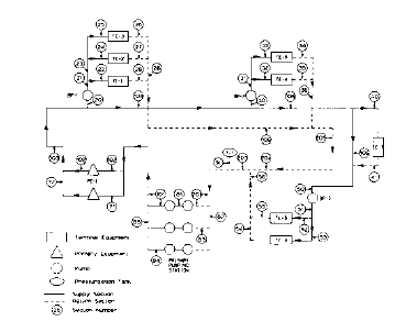
Fig. 1-3 shows a primary-secondary system. The primary pumping station consists of six pumps arranged in a 3-parallel x 2-series system. All the pumps in the pumping station are identical in type and size. This is recommended design. The flow in each pump is, therefore, one-third or the total system flow and the pressure head for each pump is one-half of the required system head.
The entire pumping station is treated as a single pressure source with a first supply (S) section (101) leaving the system and a last return (R) section (201) entering the system. All the other sections in the pumping station are identified as X sections that must be excluded from the network analysis.
Fig. 1-3 : Primary-Secondary System
The piping network identification information from Fig. 1-3 is shown in tabular form in Fig. 1-4. This information is rearranged and presented in Fig. 1-5 through Fig. 1-9 as circuits with the sections in each circuit arranged in flow sequence.
Fig. 1-5 shows complete circuits starting from the primary pumping station, passing through a terminal equipment and back to the pumping station. This is the typical circuit arrangement when there are no booster pumps.

Fig. 1-4: Piping Network Identification Information
Fig. 1-6 is the primary system and Fig. 1-7, Fig. 1-8 and Fig. 1-9 are the secondary systems. Note that the circuit that passes through the terminal equipment having the label TE-6 does not have a booster pump. That entire circuit becomes a part of the primary system.
| Ckt No. | # of Sect | Sections in Each Circuit Arranged in Flow Sequence | |||||||||
| 1 | 4 | 101 | 102 | 103 | 20 BP-1 | ||||||
| 2 | 5 | 101 | 102 | 103 | 104 | 30 BP-2 | |||||
| 3 | 10 | 101 | 102 | 103 | 104 | 105 | 40 TE-6 | 41 | 204 | 203 | 201 BP-2 |
| 4 | 7 | 101 | 102 | 103 | 104 | 105 | 106 | 50 BP-3 | |||
Fig. 1-6: Primary System Identification
| Ckt No. | # of Sect | Sections in Each Circuit Arranged in Flow Sequence | |||||||||
| 1 | 8 | 21 | 22 TE-1 | 29 | 206 | 205 | 204 | 203 | 201 | ||
| 2 | 10 | 21 | 23 | 24 TE-2 | 27 | 28 | 206 | 205 | 204 | 203 | 201 |
| 3 | 10 | 21 | 23 | 25 TE-3 | 26 | 28 | 206 | 205 | 204 | 203 | 201 |
Fig. 1-7: Secondary System from Booster Pump BP-1
| Ckt No. | # of Sect | Sections in Each Circuit Arranged in Flow Sequence | |||||||
| 1 | 8 | 31 | 32 TE-4 | 35 | 36 | 205 | 204 | 203 | 201 |
| 2 | 8 | 31 | 33 TE-5 | 34 | 36 | 205 | 204 | 203 | 201 |
Fig 1-8: Secondary System from Booster Pump BP-2
| Ckt No. | # of Sect | Sections in Each Circuit Arranged in Flow Sequence | |||||
| 1 | 6 | 51 | 52 TE-7 | 55 | 56 | 293 | 201 |
| 1 | 6 | 51 | 53 | 54 | 56 | 203 | 201 |
Fig. 1-9: Secondary System from Booster Pump BP-3
| Ckt No. | # of Sect | Sections in Each Circuit Arranged in Flow Sequence | |||||||||||||
| 1 | 12 | 101 | 102 | 103 | 20 BP-1 | 21 | 22 TE-1 | 29 | 206 | 205 | 204 | 203 | 201 | ||
| 2 | 14 | 101 | 102 | 103 | 20 BP-1 | 21 | 23 | 24 TE-2 | 27 | 28 | 206 | 205 | 204 | 203 | 201 |
| 3 | 14 | 101 | 102 | 103 | 20 BP-1 | 21 | 23 | 25 TE-3 | 26 | 28 | 206 | 205 | 204 | 203 | 201 |
| 4 | 13 | 101 | 102 | 103 | 104 | 30 BP-2 | 21 | 32 TE-4 | 35 | 36 | 205 | 204 | 203 | 201 | |
| 5 | 13 | 101 | 102 | 103 | 104 | 30 BP-2 | 21 | 33 TE-5 | 34 | 36 | 205 | 204 | 203 | 201 | |
| 6 | 10 | 101 | 102 | 103 | 104 | 105 | 40 Te-6 | 41 | 204 | 203 | 201 | ||||
| 7 | 13 | 101 | 102 | 103 | 104 | 105 | 106 | 50 BP-3 | 51 | 52 TE-7 | 55 | 56 | 203 | 201 | |
| 8 | 13 | 101 | 102 | 103 | 104 | 105 | 106 | 50 BP-3 | 51 | 53 TE-8 | 54 | 56 | 203 | 201 | |
Fig. 1-5: Complete System Identification
TE- < number > = Terminal Equipment No. BP- < number > = Booster Pump No.
Closed and Open Piping Network Systems

| Fig 1-10: Closed System |

| Fig1-11: Open System |
Closed systems are made up of two components:
- a supply system that ends at a terminal air conditioning equipment unit
- a return system that starts at the terminal equipment
Fig. 1-10 shows a closed system network. The system shown is a reverse return system with both supply and return sections. Closed systems are not affected by atmospheric pressure. The pump head of open systems include atmospheric pressure. Fig. 1-11 illustrates an open supply system.
Network Analysis
The piping system analysis uses a general tree structure. A pipe network can be either an open or closed network. To simplify analysis, a closed network can be divided into two open networks, one supply and one return, with the break between them at the terminal equipment.
An open network can be analyzed as a tree with a single trunk fanning out into branches, subbranches, then leaves. Forward network analyses begin with the main pump (tree trunk) and work down each pipe section (branch, sub-branch) to a terminal equipment (leaf). Reverse network analysis works from a terminal equipment to the pump.
The tree structure is handled as a number of linear linked lists, one for each junction in the pipe network. A pipe section is analyzed only once and and the sections are arranged in flow sequence into complete circuits.
The pipe sections are linked into circuits. A supply section can have only one upstream section and any number of downstream sections. A return section can have only one downstream section and any number of upstream sections.
The network analysis to determine the fluid flow in each pipe section starts with each terminal equipment, a circuit end, and moves backwards, assigning the fluid quantity of the terminal equipment to all the sections in the circuit.
Thermal analysis begins with the fluid temperature leaving the primary equipment section, and moves forward through each section in the circuit. The heat gains or losses and the temperature at the end of each section are calculated.
The temperature at the end of the last section in the circuit is the actual fluid temperature at the terminal equipment. The pressure analysis also moves forward through the network, starting at the pump section.
Fig. 1-12 through Fig. 1-16 are examples of basic liquid system. The systems described in the next few pages use water, although brine and glycol may be substituted in the piping network system.
Two-Pipe Direct Return Systems
A two-pipe direct return system illustrated in Fig. 1-12 is difficult to balance because the terminal equipment with the shortest supply line also has the shortest return line. The circuit analysis report will indicate the balancing requirements of each circuit.

| Fig. 1-12:Two-Pipe Direct Return |
Two-Pipe Reverse Return Systems
A two-pipe reverse return system illustrated in Fig. 1-13 provides uniform pressure drop through all the heating units. The length of straight piping through all the circuits is approximately the same. The unbalanced pressure heads are primarily due to equipment and fitting losses in the circuits.

| Fig. 1-13: Two-Pipe Reverse Return |
Primary-Secondary Systems and Loops
By definition, a secondary system is created when a booster pump is located in one of the sections. Fig. 1-3 shows a primary system with three secondary systems downstream of these booster pumps.
Fig. 1-14 shows a reverse-return primary loop and direct-retur secondary loops. Since there are no booster pumps, the entire network is treated as one primary system.

| Fig. 1-14: Primary-Secondary Systems and Loops |
Primary loops may be direct-return or reverse-return. They may be combined with one or more secondary loops that may all be direct-return, reverse-return, or a combination of the two.
From Fig. 1-13 and Fig. 1-14, you can see that secondary systems are also secondary loops, but secondary loops are not always secondary systems.
Three-Pipe Systems
The three-pipe system illustrated in Fig. 1-15 uses two piping systems to supply the terminal equipment, one for cold water and the other for hot water, along with a common return.

| Fig. 1-15: Three Pipe Systems |
The three-pipe system may be terminal mix or return mix. In both types, hot and cold water is provided at the terminal equipment. In the terminal mix system, hot and cold water are mixed at the terminal equipment to obtain the required equipment temperature.
In the return mix system, each terminal equipment in the network uses either hot water or cold water and discharges into a common return system where mixing takes place.
Four-Pipe Systems
The four-pipe system, illustrated in Fig. 1-16, derives its name from the four pipes to and from each terminal equipment: cold water supply, cold water return, hot water supply and hot water return. The four-pipe system satisfies the variations in the heating and cooling loads by providing independent sources of heating and cooling to the room or zone. During the period between seasons, any unit can be operated at maximum heating or maximum cooling.

| Fig. 1-16: Four Pipe Systems |
Systems
Systems types are based on the application, fluid type and piping arrangement (open or closed)
| System Group | System Type | System Open/Closed | Fluid Type | Network Type | System Description |
| Liquids | CW HW C DCW DHW | closed closed open closed closed | water water water water water | closed closed closed open open | chilled water hot water heating condenser water domestic cold water domestic hot water |
| GLYCOL BRINE DIESEL GASOLINE HTHW | closed closed closed closed closed | glycol brine diesel gasoline water | closed closed open open closed | 50% ethylene glycol 25% calcium chloride brine diesel fuel oil #2 gasoline (petrol) high temperature hot water | |
| Steam | STEAM CONDENSATE | closed open/closed | steam steam | open open | steam supply steam condensate return |
| Gas | FUELGAS | closed | fuel gas | open | |
| Other | STORM DRAIN VENT | open open open | water --- air | open open open | storm drainage sanitary drainage sanitary vent |
Fig. 1-17: System, Fluid and Network Types
| System Group | Engineering Units | Remarks | ||
| Flow | Velocity | Pressure | ||
| Liquids | gpm | ft/sec | ft of liquid | psia where appropriate |
| Steam | lb/hr | ft/min | psi | |
| Gas | cfh | ft/min | psi | |
| Other | fixture units or drainage area | |||
Fig. 1-18: System Types and Engineering Units
Density and kinematic viscosity are used in frictional loss calculations. The specific heat is used in thermal analysis. Default fluids are 50% ethylene glycol, 25% calcium chloride, diesel fuel oil #2, and gasoline with a specific gravity of 0.72. In Fig. 1-19 and Fig. 1-20, the defaults shown express kinematic viscosity in 10-6. Glycol may be a different concentration of ethylene glycol or glycerol. Brine may be a different concentration of sodium chloride or calcium chloride. Diesel fuel oil and gasoline may represent different blends of these liquids.
| Liquid | Properties | Temperature oF | ||||||
| -30 | 0 | 30 | 60 | 100 | 150 | 212 | ||
| WATER | Density (lb/cu ft) Kinematic viscosity (sq ft/sec) Specific heat (Btu/lb oF) | 62.42 20.0 1.0 | 62.37 12.17 1.0 | 62.00 7.39 1.0 | 61.20 4.76 1.0 | 59.81 3.2 1.005 | ||
| GLYCOL | Density (lb/cu ft) Kinematic viscosity (sq ft/sec) Specific heat (Btu/lb oF) | 67.98 595.0 0.70 | 67.55 190.0 0.73 | 67.11 85.4 0.76 | 66.55 48.6 0.78 | 65.74 22.6 0.81 | 64.68 12.5 0.85 | 63.12 6.4 0.88 |
| BRINE | Density (lb/cu ft) Kinematic viscosity (sq ft/sec) Specific heat (Btu/lb oF) | 78.59 171.7 0.66 | 78.21 77.5 0.67 | 77.71 34.7 0.68 | 77.21 21.8 0.69 | 76.09 8.9 0.71 | 64.68 12.5 0.85 | 63.12 6.4 0.88 |
| DIESEL | Density (lb/cu ft) Kinematic viscosity (sq ft/sec) Specific heat (Btu/lb oF) | 59.2 376.7 0.47 | 57.4 161.5 0.48 | 56.1 80.7 0.49 | 54.9 48.3 0.50 | 53.0 29.1 0.51 | 51.1 7.5 0.52 | |
| GASOLINE | Density (lb/cu ft) Kinematic viscosity (sq ft/sec) Specific heat (Btu/lb oF) | 46.1 11.0 0.47 | 45.5 9.8 0.48 | 44.9 8.8 0.49 | 44.7 7.0 0.50 | 44.3 5.5 0.51 | 42.4 3.0 0.52 | |
Fig. 1-19: Properties of Liquids (Water, Glycol, Brine, Diesel and Gasoline)
High Temperature Hot Water
The temperature range for water in Fig. 1-19 is 32oF to 212oF. Fig. 1-20 shows the properties of water for the HTHW system type (high temperature hot water). The temperature range for HTHWis 212oF to 450oF. It includes the temperature range defined in the 1987 ASHRAE Handbook for medium temperature hot water (212o to 350o). An additional fluid property, saturation pressure, is included in this table and is included in the output reports for your information. The saturation pressures are not used in the calculations.
| Temperature | Saturation Pressure PSIG | Density lb/cu ft | Kinematic Viscosity sq ft/sec | Specific Heat Btu/lb oF |
| 212 | 0 | 59.81 | 3.2 | 1.0055 |
| 220 | 2.5 | 59.63 | 3.0 | 1.0068 |
| 240 | 10.3 | 59.10 | 2.7 | 1.0104 |
| 260 | 20.7 | 58.51 | 2.5 | 1.0148 |
| 280 | 34.5 | 57.94 | 2.3 | 1.020 |
| 300 | 52.3 | 57.31 | 2.1 | 1.26 |
| 350 | 119.9 | 55.59 | 1.9 | 1.044 |
| 400 | 232.6 | 53.65 | 1.7 | 1.067 |
| 450 | 407.9 | 51.55 | 1.5 | 1.095 |
Fig. 1-20: Properties of High Temperature Hot Water
Properties of Steam
Fig. 1-21 and Fig. 1-22, compiled from information published in Flow of Fluids, Crane, pp. A-2, A- 9, A-12 to A-14, show the properties of steam. Portions of this information can also be found in manufacturers' steam tables. The information in this table is used in the thermal analysis to determine the quality of steam
Fig. 1-21 & 1-22: Properties of Steam

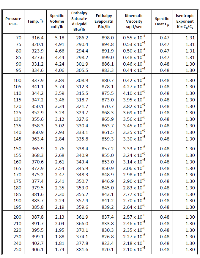
Fig. 1-21 & 1-22: Properties of Steam
Pipe Materials
| Material Code | Description | Material Code | Description | |
| S40 | Schedule 40 steel | CI 250 | 250 psi cast iron | |
| S80 | Schedule 80 steel | CK | Type K copper | |
| ST | Standard weight steel | CL | Type L copper | |
| XS | Extra strength steel | CM | Type M copper | |
| CI 125 | 125 psi cast iron | PVC | PVC schedule 40 plastic | |
| CI 175 | 175 psi cast iron | CPVC | CPVC schedule 40 plastic | |
Fig. 1-23: Pipe Materials
The default information in the pipe materials library was compiled from the Hydraulic Institute Engineering Data Book and the Hydraulic Handbook, Colt Industries. It can vary slightly with manufacturer. Density (lb/cu ft) is used to calculate the weight of a pipe section. Conductivity (btu/hr.oF.sp ft. in) is used in the thermal analysis. Inside roughness factors (ft) for open and closed piping systems are used in the Colebrook equation to calculate the frictional loss in the pipe .
| Pipe Material | Description | Nominal Diameter | Roughness Factor | Density | Conduc t-ivity | ||
| Minim | Maxim | Closed | Open | ||||
| S40 | Steel: Schedule 40 | .250" | 24" | .00015 | .0018 | 489.02 | 2.5 |
| S80 | Steel: Schedule 80 | .250" | 24" | .00015 | .0018 | 489.02 | 2.5 |
| ST | Steel: Standard Weight | .250" | 36" | .00015 | .0018 | 489.02 | 2.5 |
| XS | Steel: Extra Strength | .250" | 36" | .00015 | .0018 | 489.02 | 2.5 |
| CI 125 | Cast Iron: 125 psi | 3" | 48" | .00085 | .0018 | 483.84 | 0.767 |
| CI 175 | Cast Iron: 175 psi | 3" | 48" | .00085 | .0018 | 483.84 | 0.767 |
| CI 250 | Cast Iron: 250 psi | 6" | 36" | .00085 | .0018 | 483.84 | 0.767 |
| CK | Copper: Type K | .250" | 12" | .000005 | .000005 | 558.14 | 16.33 |
| CL | Copper: Type L | .250" | 12" | .000005 | .000005 | 558.14 | 16.33 |
| CM | Copper: Type M | .375" | 12" | .000005 | .000005 | 558.14 | 16.33 |
| PVC | Plastic: PVC | .500" | 12" | .000005 | .000005 | 94.7 | 0.1 |
| CPVC | Plastic: CPVC | .500" | 6" | .000005 | .000005 | 105.7 | 0.079 |
Fig. 1-24: Pipe Material Properties
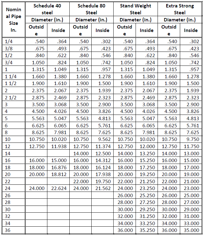
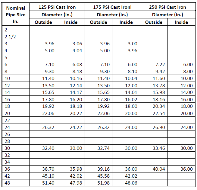
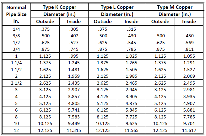
The minimum and maximum nominal diameter limits shown in Fig. 1-24 indicate the range of sizes in Fig. 1-24, Fig. 1-26, Fig. 1-27, and Fig. 1-28. These figures contain inside and outside diameters for each pipe material and each nominal size. A blank in these tables indicates that the nominal size for that particular pipe material is not available.
Roughness Factors
Roughness factors shown in Fig. 1-24 for closed pipe systems were obtained from ASHRAE Handbook: 1985 Fundamentals, Table 2, p. 2-10. Piping for open systems such as cooling tower water systems is subject to corrosion and scaling over a period of time. Open system roughness factors are included in the library, even though they are not a property of the pipe material but a function of the usage and age of the pipes. The value shown in Fig. 1-24 for Schedule 40 steel is based on Handbook of Air-Conditioning System Design, Chart 4, p. 3-23. The Colebrook-White equation shown as equation 20 in Pipe Sizing was applied using trial values for the friction factor f until results approximated those of that chart.
Values for other steel pipes and for cast iron pipes are assumed to be the same as those for the Schedule 40 steel pipes with the same age and usage. The effect of corrosion on copper pipes is assumed to be negligible. Plastic pipes are not affected by corrosion. The values shown in Fig. 1- 24 are identical for both closed and open systems.
Physical Dimensions
Fig. 1-25: Pipes Material Physical Dimensions - Steel
(adapted from Hydraulic Institute Engineering Data Book, pp. 121-127)
Fig. 1-26: Pipes Material Physical Dimensions - Cast Iron
(Hydraulic Handbook, Colt Industries, p. 174)
Fig. 1-27: Pipes Material Physical Dimensions - Copper
(reproduced with permission from ASPE Data Book, P. 10-8, 10-10, 10-12)
Fig. 1-28: Pipes Material Physical Dimensions – Plastic
Pipe Age
Fig. 1-29 shows the correction factor that can be applied to the frictional loss in order to account for the age of the pipe. This factor is a function of the pipe size (surface areas to flow area). Fig. 1-29, is based on Hydraulic Handbook, Colt Industries, Table 6, p. 64, has been modified for pipes used in buildings. Pipe age factors and pipe material roughness factors are closely related. You can use the correction factor to design closed systems with any pipe material. The roughness factors for pipes shown in Fig. 1-24 are for new and clean pipes and does not account for the age of the pipe.
| Age of Pipes (Years) | Small Pipes (1" to 3") | Medium Pipes (4" to 12") | Large Pipes (14" to 48") |
| 0 | 1.00 | 1.00 | 1.00 |
| 5 | 1.40 | 1.35 | 1.30 |
| 10 | 2.20 | 1.90 | 1.60 |
| 15 | 3.60 | 2.70 | 1.80 |
| 20 | 5.0 | 3.50 | 2.00 |
| 25 | 6.30 | 4.20 | 2.10 |
| 30 | 7.25 | 4.73 | 2.20 |
| 35 | 8.10 | 5.20 | 2.30 |
| 40 | 8.75 | 5.58 | 2.40 |
| 45 | 9.25 | 5.96 | 2.60 |
| 50 | 9.60 | 6.23 | 2.86 |
Fig. 1-29: Increase in Friction Loss Due to Aging of Pipe
Insulation Types
Fig. 1-30 shows the insulation types used for piping in buildings It includes the five insulation classes with typical insulation types within each class. For information on applications for each insulation type, turn to the ASPE Data Book, Vol. 1, Fundamentals of Plumbing Design, 1983- 1984, p. 12-1. Insulation density is used to determine the weight of the insulation for the pipe section. Conductivity is used in the thermal analysis.
| Code Name | Description | Density Lbs/ft3 | Thermal Conductivity BTU / (hr • ft2 • oF per inch) | ||||||
| 0 | 30 | 75 | 100 | 200 | 300 | 400 | |||
| EL | Elastomeric Class A | 2.0 | 0.22 | 0.23 | 0.27 | 0.28 | 0.37 | 0.50 | |
| FG | Fibrous Glass Class B | 5.0 | .20 | 0.22 | 0.25 | 0.26 | 0.33 | 0.40 | 0.50 |
| UF | Urethane Foam Class C | 2.0 | 0.15 | 0.16 | 0.17 | 0.20 | 0.25 | 0.30 | |
| PF | Phenolic Foam Class D | 4.0 | 0.19 | 0.20 | 0.22 | 0.28 | 0.35 | 0.50 | |
| CS | Calcium Silicate Class E | 13.0 | 0.38 | 0.41 | 0.44 | 0.48 | |||
| MG | 85% Magnesia Class E | 12.0 | 0.35 | 0.38 | 0.42 | 0.46 | |||
Fig. 1-30: Properties of Insulation
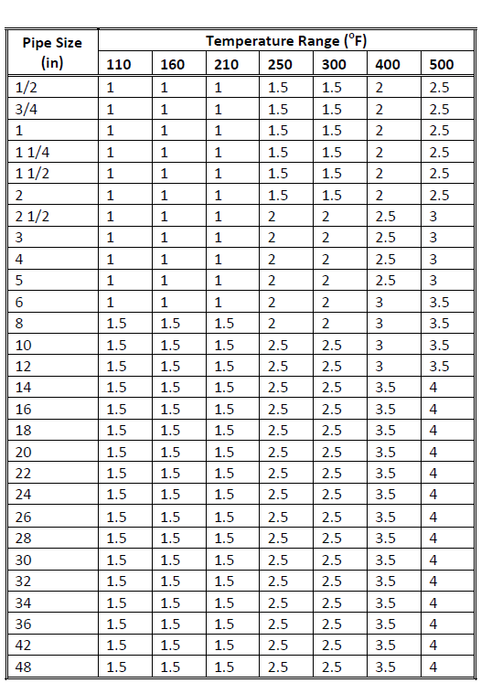
Fig. 1-31 shows an alternative way to enter the insulation thickness for each pipe section. It uses the recommended thickness for insulation code MG and pipe material code S40 as an example
Fig. 1-31: Insulation Thickness vs. Pipe Size and Temperature
Insulation Type: 85% Magnesia / Class E.
Cross-Checking Tables
Fig. 1-32 shows the various types of pipe materials used for different types of piping systems.
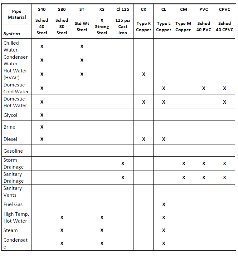
Fig. 1-32: System vs. Pipe Material
Fig. 1-33: System vs. Insulation
Fixture Unit Data:
Fixture units are used to estimate the flow quantities in domestic water supply and sanitary drainage systems. Fixture units are quantitative values associated with the fixture to account for the diversity of usage (not all fixtures are in use at the same time)
The total fixture unit data is used to calculate the flow rate in the main section. If a diversity factor is also entered for the main section, then first calculate the flow based on the sum of all total fixture units in the system, and multiply this flow by the diversity factor.
The remaining system analysis and design procedures are described in earlier sections of this engineering basis and are summarized below.
- A flow rate is assigned to all sections in the network based on the required flow rate at the fixtures. See Network Analysis.
- Pipe sizing options can be based on pressure drop per unit length, velocity or maximum flow. See Sizing Criteria.
- The Colebrook-White and Darcy-Weisbach equations are used to calculate the pressure losses through pipe sections. See Pipe Sizing.
- Fitting and valve loss calculations can be based on velocity pressure factors, K, or equivalent lengths, L/D. See Fittings and Valves.
- Heat gains and losses and temperature changes in the system are based on the thermal data that you can specify in the input forms. See Thermal Analysis.
- Static and dynamic heads are calculated for all nodes in the pipe network. See Circuit Pressure Analysis.
- The system can be designed to provide the minimum pressure required at fixtures and maintain the maximum pressure limit at the water main. See Circuit Balancing.
- The primary pump station is analyzed if a primary pump is used to develop the pressure in the main pipe section. See Pump Performance Based on System Requirements.
- Booster pumps can be located in any supply pipe circuit to increase the pressure in the circuit. See Network Analysis.
- Pressurization tanks can be located on the discharge side of the pump, on the suction side of the pump, or at the high point of the pipe system. See Pressurization Tanks.
Sizing Criteria
The values, shown in Fig. 1-34, were obtained by reading points along lines drawn between two points in ASHRAE Handbook: 1985 Fundamentals, Figure 1, p. 34.3. The criteria is based on the following points in that figure.
| Criteria | Point 1 | Point 2 |
| Low | 3 ft/100 ft for 1/2-in. pipe | 10 ft/sec for 24-in. pipe |
| Design | 5 ft/100 ft for 1/2-in. pipe | 12 ft/sec for 24-in. pipe |
| High | 7 ft/100 ft for 1/2-in. pipe | 15 ft/sec for 24-in. pipe |
| Maximum | 8 ft/100 ft for 1/2-in. pipe | 18 ft/sec for 24-in. pipe |
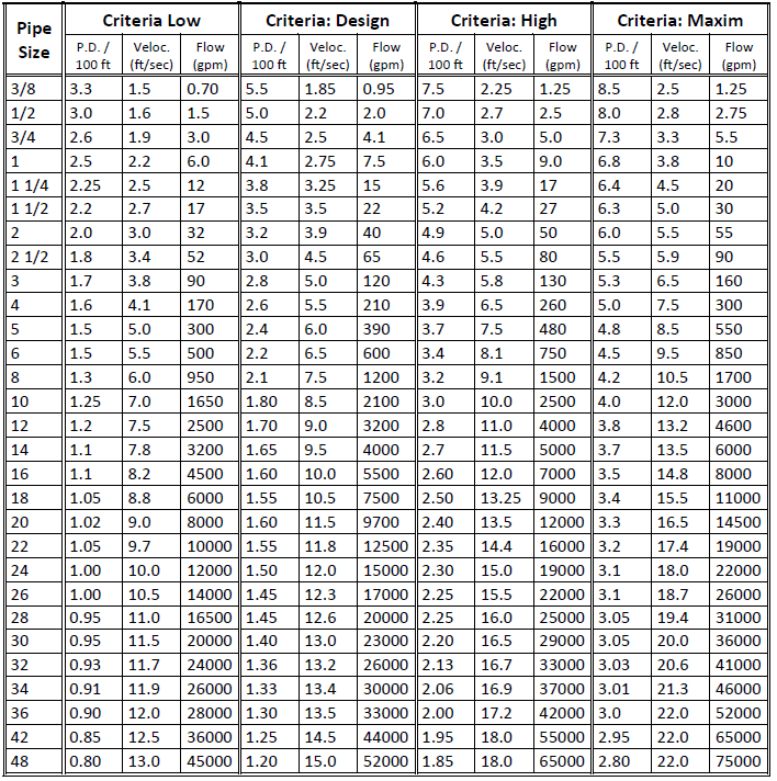
Fig. 1-34: Pipe Sizing Criteria
Fittings and Valves
Dynamic Pressure Losses
Dynamic pressure losses are a function of the geometry of the fitting or valve, and the flow velocity. There are two methods for determining the dynamic pressure losses through valves and fittings. In the first method, the velocity pressure is multiplied by a resistance factor K. The K factor is a function of the fitting or valve type and its diameter.

| where: | PD | = pressure drop through fitting or valve |
| K | = resistance factor for fitting or valve | |
| V | = fluid velocity | |
| 2g | = gravitational constant |
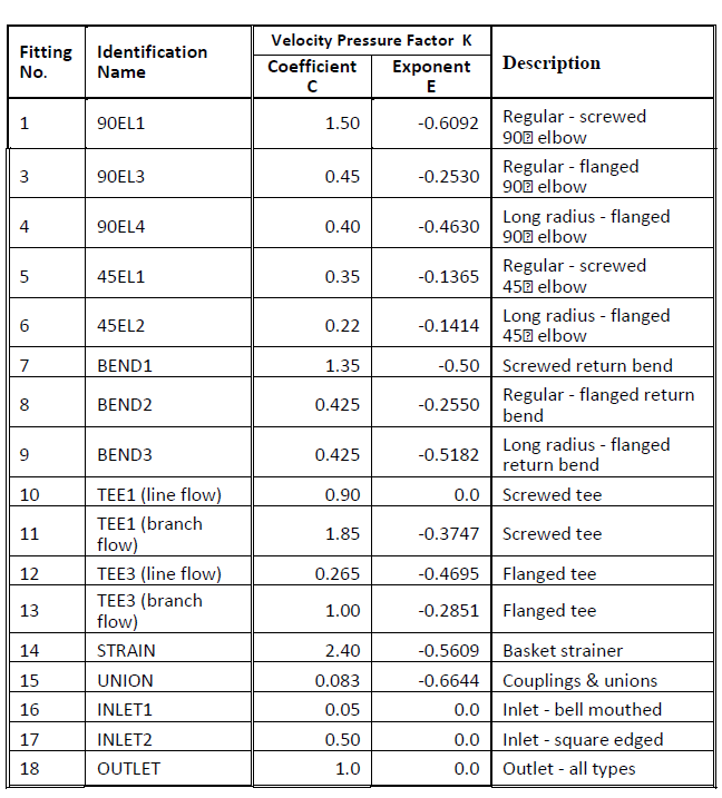
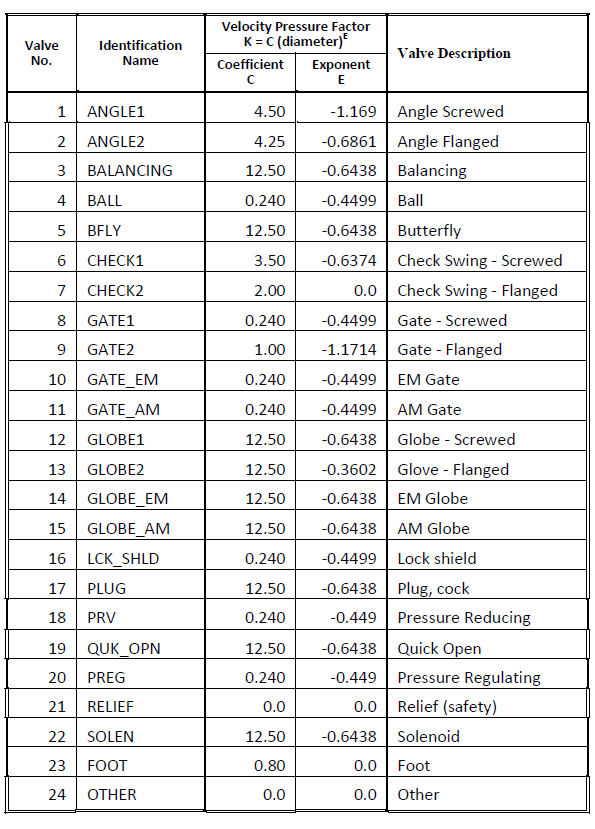
Fig. 1-35 and Fig. 1-36 show the coefficient C and exponent E for the equation that determines the resistance factor K at varying diameters. The equation is:
K = C • (diameter )E
Default values for C and E are shown in Fig. 1-35 and Fig. 1-36.
Values for water were estimated by reading off points from graphically presented data in the Hydraulic Institute Engineering Data Book, pp. 58 and 59. That data is reproduced with permission in Fig. 1-39 and Fig. 1-40 in this engineering basis.
Another method to estimate pressure losses in valves and fittings is to use equivalent length to diameter (L/D) ratios for different fluid types. Fig. 1-37 and Fig. 1-38 show default L/D. All values are approximations.
The pressure loss through the fitting or valve is the frictional loss through an equivalent length of pipe calculated using the Colebrook and Darcy-Weisbach equations.

| where: | L | = length (ft) |
| D | = diameter (ft) | |
| d | = diameter (in.) |
The K factor for 90o bends of uniform diameters is shown in Fig. 1-41 (reproduced with permission from the Hydraulic Institute Engineering Data Book, 1979). The K factor for enlargement and contractions is obtained from these equations:

| where: | θ | = Angle of convergence or divergence in enlargements or contractions in pipes |
| β | = Ratio of smaller to larger pipe diameter |
Fig. 1-35: Typical Fitting K Factors: S40 Pipe and Water (pressure loss calculation)
Fig. 1-36: Typical Valve K Factors: S40 Pipe and Water (pressure loss calculation)
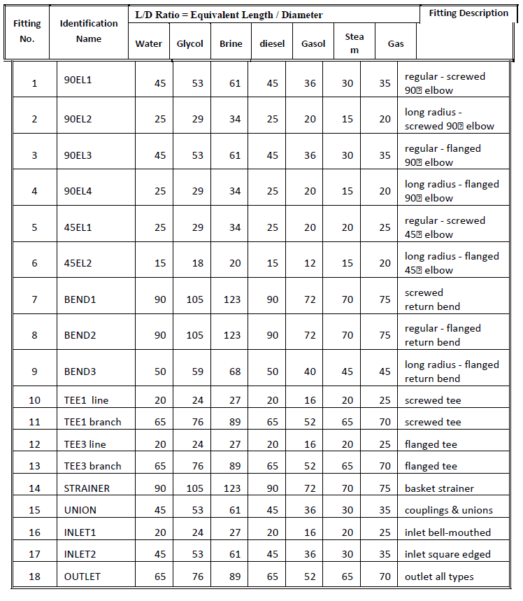
Fig. 1-37: Typical Fitting Equivalent Length Data ( L/D Factors)

Fig. 1-38: Typical Valve Equivalent Length Data

Fig. 1-39 & Fig 1-40: Resistance Coefficients of Fittings & Valves
| Fig. 1-41: Resistance Coefficients of 90o Bends Pressure Drop Through Control Valves |

|
Liquids
Control valves are associated with sections with terminal equipment. The valve flow coefficient Cv is defined as the flow in U.S. gallons per minute of water at 60oF with a pressure drop of 1 psi. Cv is a measure of the valve flow capacity and is determined by flow tests.

| where: | Q | = flow (GPM) |
| Cv | = valve flow coefficient | |
| PD | = pressure drop through valve at full flow and standard conditions (psi) | |
| ρ | = weight density of fluid (lb/cu ft) |
The pressure drop for water and liquids at other temperatures is calculated using the equation:

| where: | PD | = pressure drop through valve (psi) |
| ρ | = density of liquid (lb/cu ft) | |
| ν | = kinematic viscosity (sq ft/sec) | |
| I,s | = subscripts representing given liquid and standard liquid (water at 60oF) |
The pressure drop in psi is converted to feet of liquid with the equation:

where: PD = pressure drop through valve (liquids)
Steam
The equation for pressure drop for steam at full flow using the valve flow coefficient is:

| where: | PDst | = pressure drop through valve (psi) |
| Q | = flow rate through section (lb/hr) | |
| Cv | = control valve coefficient | |
| P | = leaving pressure at control valve or minimum supply pressure to terminal equipment (psia) |
| Note: | A minimum supply pressure to the terminal equipment is required for Equation 11. If you do not specify a valve for this input field, the default value will be assumed. |
Domestic Water Fixtures
Terminal equipment definitions for domestic hot and cold water use the data categories shown in Fig. 1-42. The supply code for flush valve is VALVE and for flush tanks, TANK. If you use these codes, then the quantity of fixture units for the valve or tank is converted into flow GPM according to Fig. 1-43. For other fixture types, you can estimate the terminal flow GPM. Supply pressure must account for the minimum pressure and pipe size connection for the fixture.
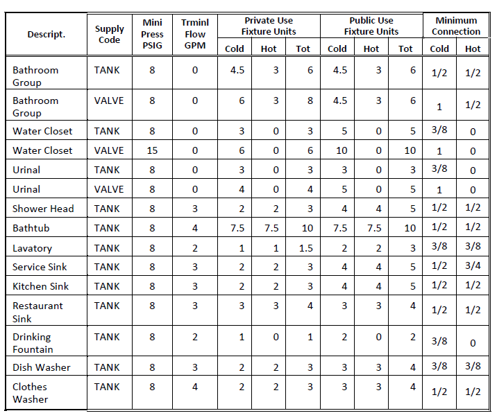
Fig. 1-42: Fixture Data: Domestic Hot and Cold Water
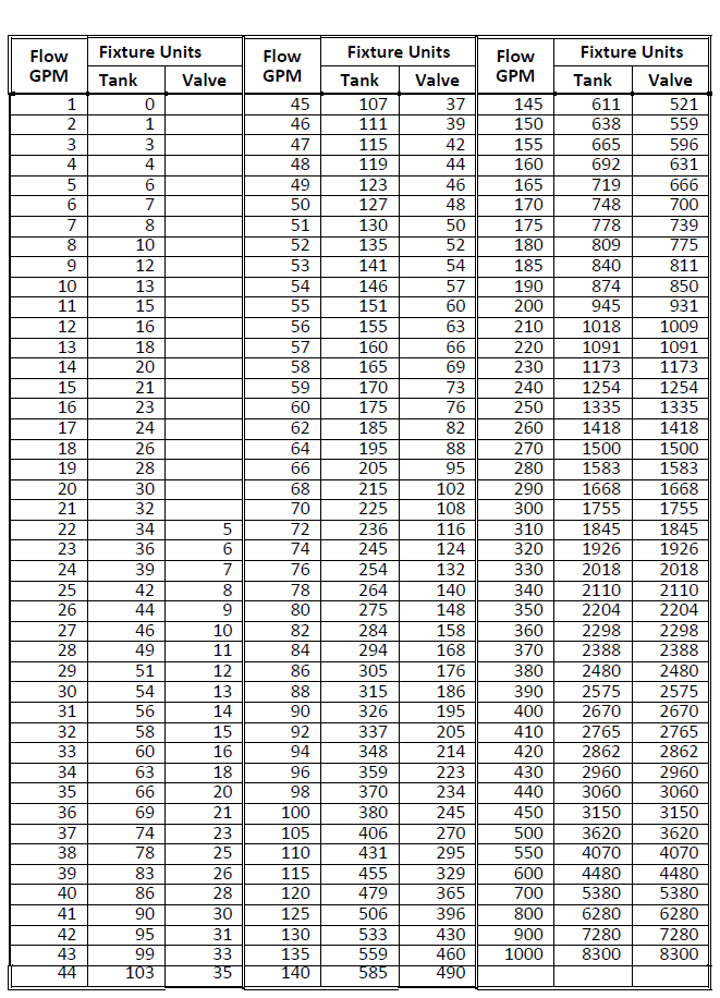
Fig. 1-43: Conversions: Gallons per Minute to Fixture Units
(reproduced with permission from ASPE Data Book, Vol. 1, p. 3-8)
Gas Appliances
Fig. 1-44 shows the approximate gas demand for common appliances. These default values were obtained from the ASPE Data Book, Vol. 1, Fundamentals of Plumbing Design, 1983-1984, p. 6-8. The heating value of the gas is used to convert the Btu/hr value into cu ft/hr flow of gas.

| Fig. 1-44: Common Appliances: Approximate Gas Demand (reproduced with permission from ASPE Data Book, Vol. 1, p. 3-8.) |
Thermal Analysis
The heat gain/loss and temperature calculation options apply to liquids and steam only.
You can choose between two options for determining the fluid temperature in each pipe section. In the first option, you can assume an average supply and return fluid temperature for all supply and return sections. This data is used to calculate the fluid properties. An example of the use of average temperatures is 200oF supply and 160oF return for a hot water heating system.
In the case of un-insulated pipes and high temperature steam and hot water, the supply temperature at each terminal must be calculated. This is done by calculating the entering and leaving temperature of each supply section, beginning with the initial temperature of the first section. The first section must be identified. In the case of liquids, the first section is the section downstream of the pump station.
The entering temperature of any supply section is the leaving temperature of the upstream section. You can reset the leaving section temperature for sections that have primary equipment.
The following equations are used to calculate liquid and steam heat gains and losses:

| where: | Qs | = rate of heat transfer per square foot of outer surface (Btu/hr sq ft) |
| Tavg | = average temperature of section (oF) | |
| Tamb | = temperature of ambient air (oF) | |
| Ri | = inside radius of pipe, (in.) | |
| Ro | = outside radius of pipe, (in.) | |
| Rs | = outside radius of insulation (in.) - Ro + insulation thickness | |
| K1 | = thermal conductivity of pipe (Btu in./hr sq ft oF) | |
| K2 | = thermal conductivity of insulation (Btu in./hr sq ft oF) | |
| 1/h | = outside surface resistance (hr sq ft oF/Btu in. = 0.6) |
Equation 12 is based on heat flow Equations 11 and 12 in ASHRAE Handbook: 1981 Fundamentals, p. 23.8. The average temperature of the section is the mean value of the temperatures entering and leaving the section. Since the leaving temperature is unknown, the average temperature is calculated iteratively.
Qs = qs • As
| where: | Qs | = total rate of heat transfer from pipe section (Btu/hr) |
| As | = outside surface area of pipe (sq ft) |
The temperature of the liquid flowing through the pipe section is obtained from Equation 14. The procedure for determining steam temperature changes is described in Steam Piping.
| where: | dTs | = change in liquid temperature in section (oF) |
| Fs | = flow through section (GPM) | |
| Df | = density of liquid (lb/cu ft) | |
| Cp | = specific heat of liquid (Btu/lb oF) |
Tl = Te - dTs
| where: | Tl | = temperature of fluid leaving section (oF) |
| Te | = temperature of fluid entering section (oF) |

The average temperature Tavg in Equation 12 depends on the leaving section temperature in Equation 16. The procedure consists of initializing the leaving temperature to the entering section temperature and then iterating through Equations 12 through 16 until a steady state value of Tavg occurs.
Pipe Sizing
The general principles of pipe sizing are described in the ASHRAE Handbook: 1985 Fundamentals, Chapter 34, p. 34.1. The Darcy-Weisbach and Colebrook-White equations are used to calculate the pressure drop in a pipe section due to fluid friction. The Darcy-Weisbach equation is:

| where: | Δ | = head loss due to friction (ft) |
| f | = friction factor, dimensionless | |
| D | = inside diameter of pipe (ft) | |
| L | = length of pipe section (ft) | |
| V | = average velocity (ft/sec) | |
| g | = acceleration of gravity (ft/sec2) |
The friction factor f is a function of the pipe roughness ?, inside diameter D and a dimensionless parameter, the Reynolds number.

| where: | ρ | = fluid density at given temperature (lb/cu ft) |
| μ | = dynamic viscosity of fluid (lb/ft sec) |
The ratio ?/? is the kinematic viscosity in sq ft/sec
Laminar flow exists where Re < 2100. For this condition, the friction factor f is obtained from:

Where Re > 2100, the flow is assumed to be turbulent. The Moody diagram that relates the friction factor f with Reynolds number and the relative roughness ?/D is shown in ASHRAE Handbook: 1985 Fundamentals, p. 2.10, fig. 13. The Colebrook-White equation for turbulent flow, shown in Equation 20, is used for the friction factor f.

where ε = absolute roughness of inside pipe wall (ft)
For fully rough flow, the value of Reynolds number is high and the last term in Equation 20 can be neglected. Equation 21 can be used in its place.

Equation 20 is used to calculate the friction factor f for turbulent flow. The Newton-Raphson iterative method is used to solve for f since f appears on both sides of the equation. The initial value of f for this iteration is obtained from Equation 21. As Reynolds number increases, the values from Equation 20 approach those that would be obtained by applying Equation 21 directly for fully rough flow.
Pipe sizing and the size of each pipe section depend on your criteria (See Sizing Criteria in this engineering basis). The criteria can be based on the limits for pressure loss per 100 ft, maximum velocity or maximum flow. The sizing iteration consists of comparing the pressure drop/100 ft, velocity or flow against the limits you specify. This is done for each standard pipe size, beginning with the smallest size and continuing until a size is found that meets the criteria. When the maximum pipe size limit is reached, you must use your engineering judgement to decide whether to:
- maintain the sizing criteria and increase the pipe size above the maximum limit or
- maintain the pipe size limit and calculate the new criteria for this size.
Steam Piping
Steam distribution network pipe sizing requires flow rates and sizing criteria for the pipe sections. The flow rate for dry steam or steam with a small amount of water (condensate) is in accordance with the laws of fluid flow. The flow is a function of these properties:
| Steam temperature | Pipe length |
The Darcy-Weisbach and Colebrook-White equations (Equations 17 through 21) are used to size steam pipes,. These equations are described in Pipe Sizing.
The flow of steam is automatically induced by the volume shrinkage that occurs when steam gives up its latent heat and condenses. Therefore, steam flow involves the analysis of two-phase flow. Condensate flows in the same direction as steam and must be trapped at intervals along the pipe length. Typical pressure classifications of steam in HVAC applications include
| Vacuum : | less than 0 PSIG |
| Low pressure : | 0 to 15 PSIG |
| Medium pressure | 15 to 100 PSIG |
| High pressure | 100 PSIG and above |
The basis of pressure classification is the initial pressure. Default values are shown in Fig. 1-45.
| Pressure Class Initial PSI | Initial Steam Pressure (PSIG) | Pressure Drop (PSI/100 ft) | Maximum System P.D. (PSIG) | Maximum Velocity (ft/min) | Minimum Velocity (ft/min) |
| low 3.5 | 3.5 | 0.25 | 1 | 4000 | 0.0 |
| low 12 | 12 | 0.70 | 3.4 | 4000 | 0.0 |
| medium 30 | 30 | 2 | 7.5 | 6000 | 0.0 |
| high 50 | 50 | 3 | 12.5 | 10000 | 0.0 |
| high 100 | 100 | 4 | 20 | 10000 | 0.0 |
| high 150 | 150 | 6 | 27.5 | 10000 | 0.0 |
Fig. 1-45: Steam Pipe Sizing Criteria
In addition to selecting a pressure classification, you can specify additional sizing criteria and constraints for the project including
Initial steam pressure (PSIG)
Maximum circuit pressure drop (psi)
Pressure drop per 100 ft (psi)
Maximum velocity (ft/min)
Minimum velocity (ft/min)
The maximum system pressure drop criterion is met by successively reducing the sizes of pipe sections for circuits that exceed the limit. This procedure is described in Circuit Balancing in this engineering basis.
Pipe sizing iteration consists of checking the pressure drop/100 ft and the maximum velocity of each standard pipe size of a given pipe material against your sizing criteria. This sequence begins with the smallest pipe size and continues until the required size is found or the maximum pipe size limit for the given material is reached.
The general laws of gas flow can be used in sizing steam pipes. This assumes that the steam temperature and pressure maintains the steam quality above its saturation level (gas) and the small amount of condensate in the system flows in the same direction as the steam.
In the program, you can enter graphic and text input to a steam supply system and its condensate return system simultaneously since they serve the same terminal equipment. The two systems are analyzed separately. Flow quantities for the terminal equipment are not automatically transferred from steam supply to condensate return since the quality of steam downstream of the terminal equipment depends on the equipment type, heat losses, pressure losses, steam traps, sub-cooling, and other design factors.
Return systems are described in Steam Condensate Return Piping in this engineering basis.
Changes in Steam Conditions
Fig. 1-46 shows steam flow and heat loss conditions for a pipe section

| Fig. 1-46: Changes in Steam Conditions |
The changes in steam conditions for a section are due to heat loss and pressure loss. For a given section,
| P1,P2 | = entering and leaving pressure (lbf/sq ft absolute) |
| V1,V2 | = entering and leaving specific volume (cu ft/lbm) |
| T1,T2 | = entering and leaving temperatures (oKelvin) |
| dQ | = heat loss in section (Btu/lbm) |
| dP | = pressure loss in section due to friction and fittings (lbf/sq ft) |
P1, V1 and T1 are set equal to the corresponding leaving conditions in the upstream section. The pressure loss dP is calculated using your sizing criteria. The leaving pressure is calculated using the equation:
P2 = P1 - dP
The amount of steam condensed in the pipe depends on dQ (heat loss) and dP (pressure loss). Each of these factors by itself produces condensate. Condensation results in an increase in the specific volume (expansion).
To find the temperature and specific volume due to pressure losses, you should assume polytropic expansion.

| where: | P1 and T1 | = the initial pressure and temperature |
| P2 and T2 | = the final pressure and temperature | |
| n | = index of expansion or compression, = 1.31 (approx.) for steam |

where V1 and V2 = initial and final specific volumes
If the specific volume V2 is less than the specific volume Vs2 of saturated steam at pressure P2, then the steam is wet and the dryness fraction q2, due to the pressure drop only, is the ratio V2/Vs2. The volume of liquid can be neglected.
Steam Condensate Quantity
The amount of steam condensing in the pipe is calculated from the General Energy Equation:
d Q = d U + d W
| where: | dQ | = heat gained (+ve) or lost (-ve) (Btu/hr/lbm) |
| dU | = change in internal energy | |
| dW | = work done in moving from state 1 (entry) to state 2 (exit) dQ, dU and dW in heat units |

| where: | dQ | = heat gained (+ve) or lost (-ve) (Btu/hr/lbm) |
| H1,H2 | = enthalpies at entry and exit (Btu/lbm) | |
| P1,P2 | = pressure at entry and exit (lb/sq ft absolute) | |
| V1,V2 | = specific volume at entry and exit (cu ft/lbm) | |
| n | = index of expansion or compression, = 1.31 (approx.) for steam | |
| J | = Joules Mechanical Equivalent of Work (=778) |
Equation 26 is based on the general expansion and compression law for gasses (PVn = Constant). The only unknown quantity in the equation is the enthalpy change (H2 - H1).
Equation 26 can be rearranged as

The dryness fraction of steam at the exit point 2 due to pressure loss and heat loss can be calculated from

| where: | x2 | = dryness fraction at exit |
| hf2 | = enthalpy of saturated liquid at exit (Btu/lbm) | |
| hfg2 | = enthalpy of evaporation at exit (Btu/lbm) |
The steam that condenses when it moves from entry point 1 to exit point 2 is calculated from
C2 = (1 - x2) M1
| where: | C2 | = condensate (lbm/hr) |
| M1 | = mass flow of steam at entry (lbm/hr) |
The procedure assumes that the condensate at the exit point 2 of the pipe section is trapped and removed from the system. The quantity of steam remaining at point 2 is now the quantity entering the next section or sections (junction).
If point 2 is a junction, then the remaining quantity of steam is divided between the downstream sections in proportion to the original required flow of steam through those sections.
Steam Condensate Return Piping
The basis for sizing steam condensate return systems is found in the ASHRAE Handbook: 1985 Fundamentals, Chapter 34, p. 34.15. Steam condensate return piping systems are analyzed as a separate stand-alone system that is independent of the steam supply systems.
Definitions
Wet Return Systems: The return pipe contains only the liquid. There is no flash vapor. This can occur when the condensate entering the trap is sufficiently subcooled. It can also occur when the liquid and vapor are separated and the wet return line is kept below the boiler water so that only liquid can flow through the line.
Dry Return Systems: The condensate piping contains both saturated liquid and saturated vapor. This is typical of most condensate return systems.
Open Return Systems: The system can be wet or dry. It is vented to the atmosphere and the condensate line is essentially at atmospheric pressure. The driving force for returning condensate is gravitational acceleration and the return line is sloped.
Closed Return Systems: The pressure in the condensate return line is above or below atmospheric pressure and is not vented to the atmosphere. The driving force for returning the condensate is pressure loss along the return line.
Condensate Return Systems
Condensate return types can be wet or dry and the system type can be open or closed. Wet types refer to liquid only and dry types are for vapor only. Given the flow rate and sizing criteria, the pipe sizes can be determined using the methods described below.
Sizing Methods
Wet Closed Return: The Darcy-Weisbach and Colebrook-White equations are used to size the pipe. The sizing criterion is pressure drop per 100 ft. or maximum velocity. Equation 31 is the Darcy-Weisbach equation modified for steam condensate return.

| where: | ΔP | = pressure drop (lb/in2) |
| f | = friction factor (dimensionless) | |
| L | = length of pipe section (ft) | |
| D | = inside diameter of pipe (ft) | |
| ρ | = density of saturated liquid or saturated vapor | |
| V | = average velocity (ft/sec) | |
| gc | = units conversion factor = 32.2 |
Typical design pressure losses per unit length (ΔP/L) are in the range of 1/16 psi to 1 psi per 100 ft. The velocity for liquid condensate systems should not exceed 150 ft/min. For vapor systems, the velocity should not exceed 7000 ft/min. The friction factor f is calculated from the Colebrook-White equation as described in Pipe Sizing in this engineering basis.
| Pipe Slope in. / 10 ft | 0.5 | 1.0 | 1.5 | 2 | 3 | 4 | 5 |
| Pressure Drop psi / 100 ft | 0.18 | 0.361 | 0.540 | 0.722 | 1.084 | 1.44 | 1.805 |
Fig. 1-47: Equivalency Between Sloped and Horizontal Flows
(reproduced with permission from ASHRAE Handbook: 1985 Fundamentals, Table 18, p. 34.16)
Fig. 1-47 illustrates that for increasing pipe slopes, the pressure drop/100 ft criterion also increases and you end up with a successively smaller pipe.
Dry Open Return: This method is the same as wet open return. The fluid is assumed to be vapor. The pipe slope is assumed to be 1 in. per 10 ft and the pressure drop/ 100 ft criterion is set at 0.361 psi. The system is vented and the flow is gravitational.
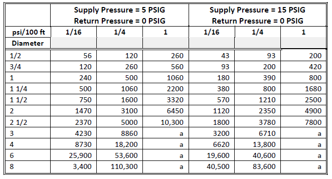
Fig. 1-48, Fig. 1-49 and Fig. 1-50 are reproduced with permission from ASHRAE Handbook: 1985 Fundamentals, Table 19, p. 34.16. For sizes and pressure losses marked a, the velocity is above 7000 ft/min.
Dry Closed Return: The condensate is assumed to be vapor. Typically, the volume fraction of vapor in the condensate is between 0.96 and 0.99. The pipe is sized from Fig. 1-48, Fig. 1-49, and Fig. 1-50, knowing the pressure drop criteria (psi/100 ft), initial supply pressure (PSIG), design return pressure (PSIG), and amount of condensate flow in the pipe section.
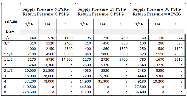
Fig. 1-48: Flow Rate (lb/hr): Dry Closed Returns
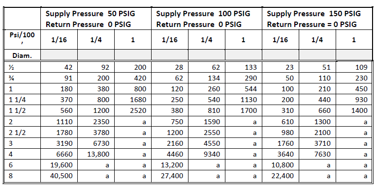
Fig. 1-49: Flow Rate (lb/hr): Dry Closed Returns, cont.
Fig. 1-50: Flow Rate (lb/hr): Dry Closed Returns, cont.
Gas Piping
To size fuel gas piping, you need to supply specific data such as:
- initial gas supply pressure
- maximum allowable pressure loss from the source to the most remote outlet
- gas consumption of each outlet
- maximum gas consumption (system diversity) at the source
- length of piping and the number and types of fittings in each section
- specific gravity of gas
Diversity in each section is an important factor in determining the correct gas pipe size.
The sizing procedure consists of a preliminary analysis to determine the longest circuit. The longest circuit is usually the circuit with the longest length of piping but is also dependent on the number of valves and fittings in the circuit. You need to add equivalent lengths of fittings and valves to obtain the longest equivalent circuit length. This is the only distance used to determine the sizes of all pipe sections in the network.
The flow capacities for various standard pipe sizes and for the longest circuit length are based on these equations:
For gas pressure not exceeding 1 PSIG

For gas pressure exceeding 1 PSIG and pipes sizes smaller than 6 in.

The constant K for a given pipe size is:

| where: | Q | = gas flow at standard condition (cu ft/hr) |
| D | = inside diameter of pipe (in.) | |
| K | = constant for given pipe diameter D | |
| h | = pressure drop (in. wg) | |
| S | = specific gravity of gas | |
| L | = total equivalent length of pipe circuit (ft) | |
| P | = pressure drop in circuit (psi) | |
| a | = average pressure in pipe (psi) |
Equations 32, 33 and 34 can be applied to all types of fuel gases provided by the gas utility industry. This includes both natural and manufactured gas. To size pipes for a particular type of fuel gas, use the specific gravity of that gas. Specific gravities for typical fuel gases include 0.67 for natural gas, 0.42 for coal gas, 0.86 for producer gas from bituminous coal, 0.47 for oil gas, and 0.55 for methane. Refer to Flow of Fluids, Crane, p. A-8 for specific gravities of other gases.
For gas pressures exceeding 1 PSIG and pipe sizes equal to or larger than 6 in.

| where: | E | = efficiency factor = 0.92 for average operating conditions |
| P1 | = pressure entering pipe network (psi) | |
| P2 | = pressure leaving pipe network (psi) | |
| Lm | = length of pipe circuit (miles) |
Sizing procedures consist of generating a table of flow rates Q for each inside pipe diameter D for a given maximum circuit pressure drop h. The initial trial length L is the measured length of the longest circuit. The size of each pipe section is selected from the table of flows in the section.
Dynamic Head
Dynamic circuit pressure analysis consists of these steps:
- add the pressure losses in each section of the circuit to obtain the circuit pressure loss
- determine the highest circuit pressure loss
- set the entering pressure of the first section in the circuit as the highest circuit loss
- analyze each section in the circuit starting with the first section and moving through each section in the fluid flow sequence
- the entering section pressure is the leaving section pressure of the upstream section
- the leaving section pressure is the entering section pressure less the section loss
- calculate the balancing required in each circuit. This is equal to the highest circuit pressure loss minus the given circuit pressure loss.
In the case of primary-secondary systems, the primary circuit ends at the booster pump on the terminal equipment if there is no booster pump in the circuit.
Secondary systems are analyzed independently as separate systems. The entering pressure of the first section in the secondary system is the pressure loss of the secondary circuit with the highest pressure loss.
Static Head
Static head calculations apply to liquids only. The static head at any point in the piping system is due to the weight of the column of liquid above that point.
The static heads at the start and end nodes of each pipe section in the piping system is estimated. The static head at any node is the difference between the highest z coordinate of all the nodes in the system and the z coordinate of the given node.
Circuit Balancing
There are two circuit balancing options:
- Balancing to maintain a maximum limit for circuit pressure loss. This option applies to steam systems only.
- Balancing to minimize the amount of throttling in the circuit. This option applies to liquid supply systems only.
Maintaining a Maximum Limit for Circuit Pressure Loss
The limiting criteria used in the balancing procedure is the minimum velocity limit for each nominal pipe size. The iteration procedure is:
- Calculate pressure loss through all circuits.
- Sort the circuits in ascending order of pressure loss and find the circuit with the highest pressure loss.
- If the highest circuit pressure loss is less than the maximum allowed, exit the iteration routine.
- Calculate the pressure loss reduction required in the circuit with the highest pressure loss (circuit pressure loss ─ maximum allowed).
- Move through the circuit in sequence from the last section with terminal equipment to the first supply section.
- If the given section has an override size, proceed to the next upstream section.
- Increase pipe size by one nominal size.
- Calculate new pressure loss in this section and the pressure reduction in the circuit.
- If required circuit pressure reduction is not satisfied, repeat steps 5b and 5c until upstream section size or minimum velocity is reached.
- When upstream section size is reached, repeat steps 5a through 5d for the next upstream section until the first section is reached.
- For the first section, repeat steps 5a through 5c until the required circuit reduction is satisfied or the minimum velocity is reached.
- Check if all the sections have reached minimum velocity (ignore override sizes). If so, exit the iteration routine.
- If maximum allowable circuit pressure loss is still not satisfied, start again with step 1.
Minimize the Throttling Required in Circuits
The limiting criteria used in this procedure are your design criteria for maximum velocity in the piping system. The iteration procedure is:
- Calculate pressure loss through all circuits.
- Sort the circuits in ascending order of pressure loss and find the circuits with the highest and lowest pressure loss.
- If the circuit flag of the circuit with the lowest pressure loss indicates that the current loss cannot be further increased, exit the iteration routine.
- Calculate the pressure loss increase required in the circuit with the lowest pressure loss (highest circuit pressure loss ─ lowest circuit pressure loss).
- If the pressure loss increase from step 4 is less than or equal to 0, exit the iteration routine.
- Move through the circuit with the lowest pressure loss, in sequence, from the last section with the terminal equipment to the first supply section.
- If the given section has an override size, go to the next upstream section.
- If the section flag indicates that the section has reached maximum velocity, then go to the next upstream section.
- If the next upstream section is common to other circuits, return to step 1.
- Decrease the pipe size by one nominal size.
- Calculate the new velocity and pressure loss in the section followed by the increase in circuit pressure loss.
- If the new velocity in the section is greater than the maximum velocity, then
- Set flag indicating section size cannot be further reduced.
- Go to the next upstream section.
- Go to step 6c.
- If the required circuit pressure increase is not satisfied, then repeat steps 6d through 6f until the first section is analyzed.
- Set circuit flag indicating that the circuit has been analyzed and the circuit loss cannot be increased any further.
Pressurization Tanks
Pressurization (expansion/compression) tank sizing is based on the methods described in the 1987 ASHRAE Handbook, pp. 13.11 - 13.15. Pressurization tanks include
- Open
- Closed
Such tanks are appropriate for system types that use condenser water, chilled water, hot water, domestic hot and cold water, glycol and brine. High-temperature hot water systems can be designed up to operating temperatures of 280 F as stated in Equation 40.
Closed pressurization tank construction can be:
- A regular tank where the pressurizing air or gas is in contact with the liquid.
- A diaphragm tank where the air charge and liquid are permanently separated by a diaphragm to prevent corrosion
System Volume
Pressurization tank size is based on the volume capacity of the system. System volume is estimated in three parts:
The volume of all the pipe sections in the system. The pipe volume is converted into gallons of liquid using the density of the liquid. The liquid temperature for determining the density is the lowest temperature in the system.
The liquid storage capacity of all the equipment in the system. The volume storage capacity of the terminal equipment, primary equipment and miscellaneous equipment.
Additional contingency system volume estimated as a percentage of the system volume.
Open Tank Sizing
Open tank sizing assumes that the tank is:
vented to the atmosphere
at least three feet above the highest point in the piping system
connected to the suction side of the pump
The tank volume size in gallons is estimated as a percentage of the total system volume The minimum recommended volume is 6% in accordance with the 1987 ASHRAE Handbook.
As an alternative to sizing the tank based on the percentage of system volume, you can use the system liquid expansion volume which is the difference in volumes at the maximum temperature of the piping system and at the minimum temperature.
Closed Tank Sizing
Fill Pressure: The tank location with respect to the piping system affects the initial fill or minimum pressure Pf at the tank. The tank can be at three possible locations with respect to the system.
Tank is above the piping system
Pf = V + F + A
| where: | V | = positive venting pressure; (assumes 12 ft of liquid if not known) |
| F | = frictional piping losses from tank to pump that must be overcome to obtain positive air venting pressure (ft of liquid as specified in input) | |
| A | = atmospheric pressure (ft of liquid |
Tank is on suction side of the pump
Pf = V + H + A
| where: | H | = system static head = distance between tank and highest point of piping system |
Tank is on discharge side of the pump
Pf = V + PH + A
| where: | PH | = pump head (ft of liquid) that must be added to maintain the positive pressure at the top of the system |
In all three cases, the atmospheric pressure A is added to obtain absolute pressure You must specify either the initial fill pressure Pf or the system static head H.
Tank Sizing Equations
The following equations are used to size closed tanks:
Regular tank with operating temperatures below 160 F

| where: | Vt | = minimum volume of pressurization tank (gal) |
| E | = net pressurization of water in the system when heated from minimum to maximum temperature (gal) | |
| Pa | = pressure in pressurization tank when water first enters tank (ft of water absolute); this can be assumed to be atmospheric pressure | |
| Pf | = initial fill or minimum pressure of tank (ft of water absolute) | |
| Po | = maximum operating pressure of tank (ft of water absolute); you can specify this relief valve setting |
Regular tank with operating temperatures between 160oF and 280oF

| where: | T | = maximum average operating temperature (oF) |
| Vs | = system volume calculated from the piping system dimensions (gal) | |
| ? | Diaphragm tank |

Cold Water Tanks
Tank sizing for chilled water systems using Equation 39 will result in tanks of very small size because of the low pressurization coefficients (40o to 90oF temperature range). For that reason, closed compression tanks applied to chilled water systems are sized as follows:
Regular tank size is half the equivalent hot water size. The piping system is considered to be operating from 70oF to 200oF. Diaphragm tank size is calculated from

where e = net pressurization factor for water
The lowest temperature of chilled water equals the minimum design temperature. This can be assumed to be 35oF. The highest temperature is the highest anticipated ambient temperature The net pressurization factor e is obtained from Fig. 1-51.
| 1-51: Net Expansion Factor: (reproduced with permission from 1987 ASHRAE Handbook, Table 2, p. 13.15) |
Pump Performance Based on System Requirements
Analyses
The pump must be analyzed for the following
Total static head for open systems
Net positive suction head available (NPSHA)
Atmospheric pressure at a given altitude
Vapor pressure for liquid at a given temperature
Circuit loss on the suction side of the pump
System data
Flow and head
Domestic water flow based on total fixture units
Primary system curve of flow vs. head in tabular form
Performance required of each pump in primary pumping station
Flow and head
Brake horsepower, motor horsepower and standard motor size
Performance required of each booster pump
Flow and head
Brake horsepower, motor horsepower and standard motor size
Total Static Head for Open Systems
The total static head is based:
Static suction lift (SSL) (ft of liquid)
Static suction head (SSH) (ft of liquid)
Static discharge head (SDH) (ft of liquid)
The total static head (TSH) is calculated given the discharge head and suction lift or suction head.
TSH = SSL + SDH
TSH = SSH - SDH if SSH > SDH
TSH = SDH - SSH if SDH > SSH
Net Positive Suction Head Available (NPSHA)
NPSHA is calculated for open systems such as condenser/cooling tower systems where the water is in contact with the atmosphere, and for high temperature hot water (HTHW) systems.
In the case of open systems NPSHA is affected by the total static head. For HTHW, NPSHA is affected by high values of vapor pressure.
NPSHA has limited usage in closed piping systems, which include water, glycol and brine. For a detailed explanation, refer to Pump & System Curve Data, Bell & Gossett, p. 11.
Net Positive Suction Head (NPSH) can be defined as the head that causes liquid to flow through the suction piping and into the eye of the impeller. This head is due to either the pressure of the atmosphere or static head plus atmospheric pressure.
Required NPSH (NPSHR) is a function of the pump design. It varies among different pump manufacturers, between different pumps from the same manufacturer and with the capacity and speed of any one pump. The manufacturer supplies this quantity for the pump.
Available NPSH (NPSHA) is a function of the piping system which includes the pump. This is calculated based on the z-elevations of the liquid and piping system. The available NPSH must be equal to or greater than the required NPSH of the pump.
The pumping arrangement can be as follows:
The source of liquid is above the pump:
NPSHA = atmospheric pressure (ft) + static head on suction (ft)
- friction losses in suction piping (ft) - vapor pressure of liquid (ft)
The source of liquid is below the pump:
NPSHA = atmospheric pressure (ft) - static suction lift (ft)
- friction losses in suction piping (ft) - vapor pressure of liquid (ft)
| Altitude | Atmospheric Pressure | |
| ft | in. Hg | psia |
| 0 | 29.921 | 14.679 |
| 500 | 29.38 | 14.414 |
| 1000 | 28.86 | 14.159 |
| 2000 | 27.82 | 13.648 |
| 3000 | 26.82 | 13.158 |
| 4000 | 25.84 | 12.677 |
| 5000 | 24.90 | 12.216 |
| 6000 | 23.98 | 11.765 |
| 7000 | 23.09 | 11.328 |
| 8000 | 22.22 | 10.901 |
| 9000 | 21.39 | 10.494 |
| 10000 | 20.58 | 10.097 |
| Fig. 1-52: | Standard Atmospheric Pressure for Altitudes (In. Hg data reproduced with permission from ASHRAE Handbook: 1985 Fundamentals, Table 3, p. 6.12) |
Vapor pressure data for the given liquid and given temperature is obtained from Fig. 1-53. Default values for water from 60oF to 450oF and for diesel oil and gasoline from 0oF to 150oF are shown. The frictional losses on the suction side of the pump must be calculated as required for the NPSHA equation.
| Temp. oF | WATER | DIESEL | GASOLINE |
| -30 | |||
| 0 | 1.00 | 1.80 | |
| 30 | 3.00 | 3.80 | |
| 60 | 0.26 | 5.00 | 6.80 |
| 100 | 0.95 | 7.00 | 10.80 |
| 150 | 3.72 | 20.00 | 30.00 |
| 212 | 14.12 | ||
| 220 | 17.19 | ||
| 240 | 24.97 | ||
| 260 | 35.44 | ||
| 280 | 49.22 | ||
| 300 | 67.00 | ||
| 350 | 134.60 | ||
| 400 | 247.30 | ||
| 450 | 424.25 | ||
| Fig. 1-53: | Vapor Pressure of Liquids, psia (water data reproduced permission from Hydraulic Handbook, pp. 84-85) |
System Data
System head includes the highest circuit pressure drop in the system. It is the sum of all the pressure losses of all the sections in the circuit. Section-by-section pressure losses are calculated in both psi and feet of liquid at the entering section temperature and density of the liquid. Circuit pressure losses are obtained by summing the section losses in psi and then expressed in feet of liquid if required. This is because losses measured in feet of liquid are dependent on the density of the liquid at different temperatures.
Hc = (HCPD + PSL)• (1 + CF / 100)
| where: | Hc | = pressure head for closed systems (psi) |
| HCDP | = highest circuit pressure drop (psi) | |
| PSL | = pumping station losses not calculated in sectional analysis (psi) | |
| CF | = contingency factor (%) |
Equation 43 applies to closed systems. For open systems, the total static head in psi is added to the pressure head
Ho = Hc + TSH
| where: | Ho | = pressure head for open systems (psi) |
| TSH | = total static head as calculated |
Calculations for TSH are shown in Total Static Head for Open Systems. The system head in psi is converted to feet of liquid at the temperature of the liquid in the pump discharge pipe section.
H1 = H • 144 / D
| where: | H1 | = system head (ft of liquid) |
| H | = Hc for closed systems, or Ho for open systems | |
| D | = density of liquid at pump discharge section temperature (lb/cu ft) |
The static heads are the z axis distances from the lowest and highest point of the piping system to the primary pumping station. System flow Q1 is calculated as the flow in the discharge section of the pump station. In the case of domestic water, the flow at the pump or first section, is calculated on the basis of total fixture units, if fixture type data is entered as terminal flow.
System Curve
The primary system curve showing flow versus head is calculated from this equation:

H2 and Q2 are points on the system curve generated by varying the value of Q2. The flow vs. head table calculates 30 points. The intervals for Q2 are obtained by dividing the system flow Q1 by 20. The table, therefore, includes 10 points above the required system operating point of Q1, H1.Fig. 1-54 shows system curve construction using a table generated by Equation 46.

| Fig. 1-54: reproduced courtesy of ITT |
Primary Pump Performance Data
The primary pumping station can be any configuration of pumps in series and parallel. All pumps in a pumping station are assumed to be identical.
The flow through each pump is the system flow divided by the number of parallel pump flow paths at the station.
The head for each pump is the system head divided by the number of pumps in series in any parallel path. All parallel paths should have the same number of pumps in series.
Brake horsepower and motor horsepower are calculated from the following equations.

| where: | BHP | = brake horsepower |
| GPM | = flow through each pump | |
| H | = pump head (ft of liquid) | |
| SPGR | = specific gravity of liquid at temperature in pump discharge section | |
| PE | = pump efficiency (%) |

| where: | MHP | = motor horsepower |
| ME | = motor efficiency (%) |
Standard motor horsepower is obtained from Fig. 1-55. It is the nearest size above MHP.
| Fig. 1-55: Standard Motor Sizes (reproduced with permission from ASHRAE | |||||||||||||||||||||||||||
Secondary (Booster) Pumps
The flow through the booster pump is the flow through the section with the booster pump.
The booster pump head is the highest circuit pressure drop in the secondary system of circuits downstream of the given booster pump.
Brake horsepower, motor horsepower and standard motor size are calculated in the same way as primary pumps.
Pump Performance Based on Test Data
This section is based upon information and procedures described in the following technical bulletins:
- Parallel and Series Pump Application, Bell & Gossett Bulletin No. TEH-1065, International Telephone and Telegraph Corporation, Morton Grove, 1965.
- Pump & System Curve Data for Centrifugal Pump Selection and Application, Bell & Gossett Bulletin No. TEH-375, International Telephone and Telegraph Corporation, Morton Grove, 1967.
The Pump Curve
The results of pump performance tests are shown by means of a plotted curve that relates the flow (gpm) to the pressure head produced (ft of liquid). The manufacturer establishes the pump curve. A typical head capacity curve is shown in Fig. 1-56.

| Fig. 1-56: Pump Curve (reproduced courtesy of ITT Fluid Technology Corporation Pump & System Curve Data, Bell & Gossett, p. 3) |
| Fig. 1-57: Pump Test Performance Data: Pump Curve | ||||||||||||||||||||||||||||||||
Pump curve (plotted test data) is based on the impeller diameter and pump rpm. From this test data, the pump equations, piping methods and fluid dynamics can be used to estimate pump performance for other pump speeds (rpm) and impeller diameters (in.). This includes:
Pump affinity laws
Parallel pumping
Series pumping
Combination parallel and series pumping
Pump Affinity Laws
Pump affinity laws, as published in Pump & System Curve Data, p. 6, is used to calculate the effects of changes in impeller diameters and rotational speeds on the pump curve. These laws state that
- Pump gpm capacity varies directly as the speed (rpm) or impeller diameter ratio.
- Pump head varies directly as the square of the speed (rpm) or impeller ratio.
| Change | GPM Capacity (Q) | Ft Head (H) |
| Impeller Diameter Change D1 to D2 |

|

|
| Speed (RPM) Change R1 to R2 |

|

|
Where Q = gpm H = head D = impeller diameter R = rpm
Fig. 1-58: Pump Affinity Laws
(reproduced courtesy of ITT Fluid Technology Corporation from Pump & System Curve Data, Bell & Gossett, p. 3)
You can use the pump station and booster pump master or override forms to request a specific pump performance curve from the library. These curves are based on test impeller diameter and rpm speed. The actual pump performance curve data is calculated from the pump test curve data that you specify, and your input for impeller diameter (in.) and speed (rpm), using the pump affinity laws
In Fig. 1-58, the terms Q1 H1 and R1 refer to the test data values in the library. The terms Q1 H2 and R2 refer to your input on the pump station or booster pump master or override form. The new curve results are presented in tabular form.
Parallel Pumping
All pumps in the primary pumping station should be identical in size and type. The effect of pumps in parallel is to divide the total system flow equally among the number of parallel pump paths.
Fig. 1-59 is a schematic layout of pumps in parallel. The check valves at the pump discharge are essential to prevent any short-circuit flow or pump damage when a single pump is running. Fig. 1-60 is a graphic representation of parallel pump curve construction.

| Fig. 1-59: Parallel Pumping (reproduced courtesy of ITT FluidTechnology Corporation Parallel and Series Pump Application, Bell & Gossett, p. 2) |

| Fig. 1-60: Parallel Pumping Curve Construction (reproduced courtesy of ITT Fluid Technology Corporation Parallel and Series Pump Application, Bell & Gossett, p. 3) |
Series Pumping
All pumps in the primary pumping station are assumed to be identical. The effect of pumps in series is to divide the total system head equally among the number of pumps in series in any one of the parallel pump paths. Pump curve points for pumps in series are calculated by multiplying the head at each point by the number of pumps in series in any one of the parallel paths. The flow remains the same through each pump in series. Fig. 1-61 is a schematic layout of pumps in series. Fig. 1-62 is a practical installation of pumps in series where the pumps can be run singly or simultaneously. Fig. 1-63 is a graphic representation of series pump curve construction.

Fig. 1-61: Series Pumping
(reproduced courtesy of ITT Fluid Technology Corporation Parallel and Series Pump Application, Bell & Gossett, p. 16)

| Fig. 1-62: Series Pumping reproduced courtesy of ITT Fluid Technology Corporation from Parallel and Series Pump Application, Bell & Gossett, p. 16) |

| Fig. 1-62: Series Pumping Curve Construction (reproduced courtesy of ITT Fluid Technology Corporation from Parallel and Series Pump Application, Bell & Gossett, p. 16) |
Combination Parallel and Series Pumping
Fig. 1-64 shows a primary pumping station consisting of a combination of pumps in parallel and series. The pumps are assumed to be identical. The flow through each pump is the total system flow divided by the number of parallel paths in the station. The head for each pump is the total system head divided by the number of pumps in series in any one parallel path. Pump curve points for the combination are calculated using the test data for a single pump.

| Fig. 1-64: Combination Parallel and Series Pumping (reproduced courtes of ITT Fluid Technology Corporation from Parallel and Series Pump Application, Bell & Gossett, p. 24) |
Point of Operation
The point of operation of the pump on the combination of parallel and series pumps is the intersection of the system curve described in Fig. 1-54 and the pump curve on the combined pumping station curve. This is shown in Fig. 1-65.

| Fig. 1-65: Point of Operation (reproduced courtesy of ITT Fluid Technology Corporation from Parallel and Series Pump Application, Bell & Gossett, p. 15) |
Domestic Hot and Cold Water
Domestic hot and cold water distribution systems are analyzed as open network, liquid supply systems. Use the system code DHW or DCW. The reference libraries used by domestic water systems include:
Properties of water in the liquid properties library, as shown in Fig. 1-19.
Pipe material properties. The library includes steel, cast iron, copper, and plastic pipe materials, as shown in Fig. 1-23 through Fig. 1-28.
Frictional loss correction factors due to pipe age, as shown in Fig. 1-29.
Properties of insulation, as shown in Fig. 1-30 and Fig. 1-31.
System cross-checking tables for pipe materials and insulation, as shown in Fig. 1-32 and Fig. 1-33.
Sizing criteria based on pressure drop per unit length, velocity or flow for each nominal pipe size, as shown in Fig. 1-34.
Losses through fittings, as shown in Fig. 1-35 and Fig. 1-37.
Losses through valves, as shown in Fig. 1-36 and Fig. 1-38.
Domestic water fixture data, as shown in Fig. 1-42.
Analysis and Design Procedure
Flow rate for each fixture is entered using the deftermequip form or ovrtermequip form. The flow at the fixture can be specified as a flow rate in gpm or as a fixture type. A fixture type refers to a corresponding set of design data in the reference library, as shown in Fig. 1-42. The design data consists of:
Supply Control Code:
Control code options include flush valve, flush tank, faucet, mixing valve, or other codes you can define yourself. Faucets, mixing valves and other fixture types use the same conversion data as flush tanks, as shown in Fig. 1-43.
Minimum Pressure:
The minimum pressure required at the fixture. The primary pump static head is calculated to maintain this pressure. If a pump is not specified and the water main pressure is used, you must choose the circuit balancing analysis option to maintain the minimum pressure at the fixture and not exceed the water main pressure.
Required Flow Rate:
The required flow rate at the fixture or terminal. This value will override the supply control code and fixture units data in the reference library.
Fixture Unit Data:
Fixture unit information can be entered in the next six fields of the library form. Fixture units can be specified separately for private or public use. Fixture unit information can be further subdivided and entered separately for cold and hot water systems
The total fixture unit data is used to calculate the flow rate in the main section. If a diversity factor applies to the main section, then first calculate the flow based on the sum of all total fixture units in the system, then multiply this flow by that diversity factor.
Minimum Hot and Cold Water Connections:
The calculated pipe size if it is greater than the minimum connections in the reference library.
The remaining system analysis and design procedures are described in earlier sections of this engineering basis and are summarized below.
A flow rate is assigned to all sections in the network based on the required flow rate at the fixtures. See Network Analysis.
Pipe sizing options can be based on pressure drop per unit length, velocity or maximum flow. See Sizing Criteria.
The Colebrook-White and Darcy-Weisbach equations are used to calculate the pressure losses through pipe sections. See Pipe Sizing.
Fitting and valve loss calculations can be based on velocity pressure factors, K, or equivalent lengths, L/D. See Fittings and Valves.
Heat gains and losses and temperature changes in the system are based on the thermal data that you can specify in the input forms. See Thermal Analysis.
Static and dynamic heads are calculated for all nodes in the pipe network. See Circuit Pressure Analysis.
The system can be designed to provide the minimum pressure required at fixtures and maintain the maximum pressure limit at the water main. See Circuit Balancing.
The primary pump station is analyzed if a primary pump is used to develop the pressure in the main pipe section. See Pump Performance Based on System Requirements.
Booster pumps can be located in any supply pipe circuit to increase the pressure in the circuit. See Network Analysis.
Pressurization tanks can be located on the discharge side of the pump, on the suction side of the pump, or at the high point of the pipe system. See Pressurization Tanks.
Sanitary Drainage and Venting
The design of the sanitary drainage system is based on the fixture unit method. The reference library includes a series of look-up tables and corresponding data forms you can use to specify the data in accordance with a specific geographic location or municipal code you may need to follow. The table format was designed to accommodate various city codes throughout the United States. It should be flexible enough to allow any adjustments you make.
The sanitary drainage library tables, shown in Fig. 1-66 through Fig. 1-69, are:
- building drains and sewers
- horizontal fixture branches and stacks
- horizontal vent sizing
- vertical vent sizing
Sanitary Drainage Pipe Sizing
The following procedure is used to size sanitary drainage pipes:
The horizontal pipes, or branches, on each floor connected to a vertical stack are sized first.
The fixture types associated with each horizontal branch are converted into fixture units.
Fixture units handled by each pipe segment in the horizontal branch are calculated sequentially, starting with the last fixture and working toward the vertical stack.
The pipe size for the number of fixtures is chosen using the reference library data, as shown in Fig. 1-67.
The number of fixture units in each pipe segment in the vertical stack are calculated sequentially, starting at the highest horizontal branch.
The pipe size is determined using the values indicated in Fig. 1-67 for stacks with three or fewer branches, or for stacks with more than three branch intervals, as appropriate.
If the resulting pipe size for a vertical segment is smaller than that of the horizontal branch above it, the pipe size for the vertical segment is adjusted to match that of the horizontal branch.
The pipe size for the horizontal building drains connecting the vertical stacks is based on the slope, the fixture units handled by each pipe segment between vertical stacks, and by the corresponding column shown in Fig. 1-66.
Building Drains and Sewers
| Diameter of Pipe (in.) | Maximum number of fixture units that may be connected to any portion of the building drain or the building sewer | |||
| Slope Per Foot | ||||
| 1/16 inch | 1/8 inch | 1/4 inch | 1/2 inch | |
| 2 | 21 | 26 | ||
| 2-1/2 | 24 | 31 | ||
| 3 | 42 | 50 | ||
| 4 | 180 | 216 | 250 | |
| 5 | 390 | 480 | 575 | |
| 6 | 700 | 840 | 1000 | |
| 8 | 1400 | 1600 | 1920 | 2300 |
| 10 | 2500 | 2900 | 3500 | 4200 |
| 12 | 2900 | 4600 | 5600 | 6700 |
| 15 | 7000 | 8300 | 10000 | 12000 |
Fig. 1-66: Building Drains and Sewers
(reproduced with permission from ASPE Data Book, Vol. 1, Table 1-5, p. 1-6)
Horizontal Fixture Branches and Stacks
| Diameter Pipe (in.) | Any Horizontal Fixture Branch | One Stack of Three Branch Intervals or Less | Stacks with more than three Branch Intervals | |
| Total for stack | Total at one branch interval | |||
| 1-1/2 | 3 | 4 | 8 | 2 |
| 2 | 6 | 10 | 24 | 6 |
| 2-1/2 | 12 | 20 | 42 | 9 |
| 3 | 20 | 48 | 72 | 20 |
| 4 | 160 | 240 | 500 | 90 |
| 5 | 360 | 540 | 1100 | 200 |
| 6 | 620 | 960 | 1900 | 350 |
| 8 | 1400 | 220 | 3600 | 600 |
| 10 | 2500 | 3800 | 5600 | 1000 |
| 12 | 3900 | 6000 | 8400 | 1500 |
| 15 | 7000 | |||
| Fig. 1-67: | Horizontal Fixture Branches and Stacks (reproduced with permission from ASPE Data Book, Vol. 1, Table 1-2, p. 1-4) |
Horizontal Vent Sizing
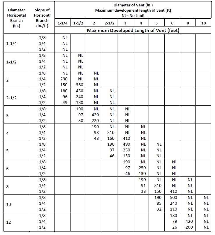
Fig. 1-68: Horizontal Vent Sizing
(reproduced with permission from BOCA National Plumbing Code, Table P-902.2, p. 61) The maximum developed length of the vent is measured from the vent connection to the open air. Where Fig. 1-68 shows NL or no limit, the default limit is 500.
Vertical Vent Sizing

Fig. 1-69: Vertical Vent Sizing
(reproduced with permission from BOCA National Plumbing Code, Table P-902.1, p. 60) The developed length is measured from the vent connection to the open air.
Sizing Procedure
Sanitary vent systems must be developed within the same graphic model as the associated sanitary drainage system, toggling back and forth between the two system types as necessary. First analyze the drainage system to obtain the drainage pipe sizes, then size the associated vent system.
Sanitary vent sizing uses the reference library look-up tables as shown in Fig. 1-68 and Fig. 1-69 Determine the length of the vent pipe from its point of connection to the drainage system to the point of vent exit. In order to use the library look-up tables, obtain the pipe size and number of fixture units at the point of connection, which is typically at the low point of the sanitary drainage vertical stack.
To size vent pipes connected to a drainage stack, read from the table in Fig. 1-69, the vertical vent stack size that corresponds to the vent pipe length, and the drainage stack diameter and fixture units that was determined from drainage pipe sizing.
To size vent pipes connected to a horizontal drainage branch, the slope for that horizontal drain is required. The size can be read from the table shown in Fig. 1-68. Vent piping section types include:
- extensions
- terminal
- header
- individual
- branch
- circuit
- relief
The same sizing procedure can be used for all vent types, with the exception of the relief vent. Relief vents use the same sizing table as horizontal vent pipes, with the drainage pipe slope as specified in the master or override form. The vent length, however, is calculated from the point of connection to the sanitary drainage stack to the point of connection to the vertical vent stack.
Storm Drainage
The design of the storm drainage system is based on the look-up table method. The reference library includes a series of look-up tables and corresponding data forms you can use to specify the data in accordance with a specific geographic location or municipal code that you may need to follow. The table format was designed to accommodate various city codes throughout the United States. It should be flexible enough to allow any adjustments you make.
The tables can be used to design continuous flow storm drainage systems. To design controlled flow systems, you will need to enter the equivalent total area per drain and rainfall rate for continuous flow.
The drain in the storm system sizing corresponds to the terminal equipment in other system types. Gutter sizing is not included in the program and storm systems that include gutters must be modified to convert the system into an equivalent system of roof drains, leaders and horizontal rainwater pipes.
The storm drainage library tables, shown in Fig. 1-70 and Fig. 1-71, are:
roof drain and leader sizing
horizontal rainwater pipe sizing
Roof Drain and Leader Sizing
| Rainfall (in./hr.) | Size of Drain or Leader Diameter (in.) | |||||
| 2 | 3 | 4 | 5 | 6 | 8 | |
| 1 | 2880 | 8800 | 18400 | 34600 | 54000 | 111600 |
| 2 | 1440 | 4400 | 9200 | 17300 | 27000 | 58000 |
| 3 | 960 | 2930 | 6130 | 11530 | 17995 | 38660 |
| 4 | 720 | 2200 | 4600 | 8650 | 13500 | 29000 |
| 5 | 575 | 1760 | 3680 | 6920 | 10800 | 23200 |
| 6 | 480 | 1470 | 3070 | 5765 | 9000 | 193315 |
| 7 | 410 | 1260 | 2630 | 4945 | 7715 | 16570 |
| 8 | 360 | 1100 | 2300 | 4325 | 6750 | 14500 |
| 9 | 320 | 980 | 2045 | 3845 | 6000 | 12890 |
| 10 | 290 | 880 | 1840 | 3460 | 5400 | 11600 |
| 11 | 260 | 800 | 1675 | 3145 | 4910 | 10545 |
| 12 | 240 | 730 | 1530 | 2880 | 4500 | 9660 |
Fig. 1-70: Roof Drain and Leader Sizing
(reproduced with permission from ASPE Data Book, Vol. 1, Table 2-1, p. 2-3) For each rainfall rate and valid nominal drain or leader diameter, you can define the area that can be drained. The area is in square feet.
Horizontal Rainwater Pipe Sizing
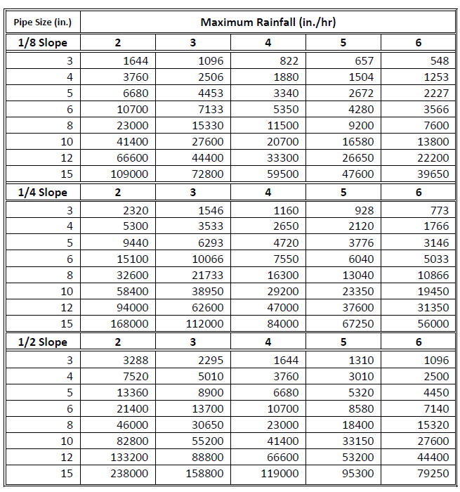
| Fig. 1-71: | Horizontal Rainwater Pipe Sizing (reproduced with permission from ASPE Data Book, Vol. 1, Table 2-4, p. 2-6) |
For each valid slope and rainfall rate, you can define the nominal pipe size and the area that can be drained. The area is in square feet.
Sizing Procedure
For storm drainage, use the input forms and place the appropriate engineering elements to specify:
The rainfall rate for the building type and location, as determined by code requirements or other design considerations.
The locations of roof drains, and their associated roof and washdown areas if those areas are different from the master values.
The slope of horizontal rainwater pipes.
The following steps are used to size storm drainage pipes:
Orientations for vertical leader pipes and horizontal pipes are determined from the graphic data.
Vertical leaders are sized using the reference library as shown in Fig. 1-70.
Horizontal pipe sizes are based on your input slope, and the maximum rainfall rate and drainage area of the drains connected to that pipe. The reference library, as shown in Fig. 1-71, is used.
If the rainfall rate is greater than the maximum in that library, an error message is generated and the maximum rate is used. For any other case, actual rates are rounded up to the nearest rate in the library if necessary.
The vertical leader size from the library is checked against the size of the horizontal pipes, if any, connected above it. If the leader is smaller, the size is adjusted to match that of the horizontal pipe.
Similarly, the horizontal pipe size from the library is checked against the size of the vertical leader, if any, connected above it. If the horizontal pipe is smaller, the size is adjusted to match that of the vertical leader.
Material Estimating
Piping system material estimation include:
Pipe material, insulation, fittings, valves and equipment quantities for each pipe section in the system
Total pipe lengths for each pipe material and pipe size used in the system
Total insulation surface areas for each insulation type and thickness used in the system
Fitting quantities for each fitting type and size used in the system
Valve quantities for each valve type and size used in the system
Turn to Appendix Two: Reports for more information on material estimation reports.
