Energy Usage Analysis of Buildings
Energy usage analysis of buildings involves four principal steps.
First is the calculation of heat loss and gain to the building spaces and the heating and cooling loads imposed upon the building HVAC systems. This calculation is carried out for a space temperature fixed in time and is commonly called the Loads calculation. It answers the question: how much heat addition or extraction is required tomaintain the space at a constant temperature as the outside weather conditions and internal activity vary in time and the building mass absorbs and releases heat.
Second is the calculation of the energy addition and extraction actually to be supplied by the HVAC system in order to meet the possibly varying temperature set-points and humidity criteria subject to the schedules of fans, boilers and chillers, and to outside air requirements. This calculation results in the demand for energy that is made on the primary energy sources of the building. This step, called the Systems calculation, answers the question: How are the accumulative heat extraction and addition rates modified, when the characteristics of the HVAC system, the time-varying temperature set-points, and the heating, cooling and fan schedules are taken into account?
Third is the determination of the fuel requirements of primary equipment such as boilers and chillers, and of the' energy production of solar collectors, etc., in the attempt to supply the energy demand of the HVAC systems. This Plant calculation answers the question: howmuch fuel and electrical input is required to feed the secondary HVAC system given the efficiency and operating characteristics of, the plant equipment and components.
Fourth step evaluates the costs of equipment, fuel, electricity, labor and retrofit components against the alternative of investing the money in other ways. It answers the question: Is the expenditure of funds for energy conserving materials and systems cost effective, when compared with alternative systems and investment possibilities? This step is called Economics calculation.
The long history of development of such calculational procedures has been justified on the basis that more accurate calculations will give improved analysis of life cycle costs of buildings,more precise sizing of equipment andmore carefully controlled operation of the primary and secondary HVAC systems. The EnergyPlus (E+) program released by the U.S. Department of Energy (USDOE) to succeed the DOE2 program allows time step intervals as small as 10 minutes. The value of such small time steps affects heat gains and losses through the building envelope. However, weather data and operating profiles (schedules) are provided in hourly intervals and for most building energy studies, a time step interval of one hour is accurate enough.
Besides the DOE2 and EnergyPlus programs developed by USDOE, there are three other major privately developed energy programs. eQUEST is an expansion of the last version of DOE2.2 with a windows interface. TRACE is offered by the Trane Company and HAP by Carrier Corporation. Trane and Carrier are the two largest manufacturers of heating, ventilating and air conditioning equipment (HVAC). Both programs have a windows interface and an extensive library of building envelope and HVAC equipment performance data.
Uses for Energy Analysis Programs
Programs that expect you to fill out forms tend to be less flexible than the DOE2 programwhich has a Fortran- English like language to describe the buildingmodel. Because of the flexibilityof its input, theDOE-2 program, in particular, can be of assistance in many applications, especially the consideration of energy conserving alternatives and in building and systems design:
(1) Energy Conservation Studies
- Effect of the thickness, order and type of materials and orientation of exterior walls and roofs;
- Effect of thermal storage in walls and floors and in water tanks coupled to HVAC systems;
- Effect of occupant, lighting and equipment schedules;
- Effect of intentionally undersized secondary HVAC systems and central plant equipment.
- Effect of the thermal environment of various zones during spring and autumn, when the heating or cooling demand is small, yet energy consumption does not reflect these low demands;
- Effect of intermittent operation, such as the shutdown of HVAC systems during the night and/or on weekends and holidays or for any hour during the day;) Effect of reduction in minimum outside air requirements; scheduled use ofoutside air for cooling;
- Effect ofinternal and external shading, tinted and reflective glass;
- Off-peak heating or cooling of buildings to reduce peak heating or cooling electric demand;
- Active solar collector/storage systems for heating and cooling;
- Heat recovery strategies to eliminate wastage of rejected heat.
(2) Building design studies
- Initial design selection of the basic elements of the building, primary and secondaryHVAC systems, and energy source;
- Evaluation, during the design stage, of specific design concepts and modifications, including optimal system zoning, optimal control strategies, and optimal systems selection;
- Evaluation, during construction, of contractor proposals for deviations from the construction plans and specifications;
- Monitoring the operation and maintenance of the finished building to provide the greatest return on energy investment;
- Analysis of existing buildings for cost-effective retrofits;
- Analysis of electric load management schemes as applied to single buildings or multi-building complexes.
- Comparison of loads and equipment selections using design day features versus those that result fromweather tapes;
- Evaluation of a building's compliance with the Design Energy Budget as established by the Congessionally mandated Building Energy Performance Standards.
DOE-2 Structure
DOE-2 comprises one translation and library program and four simulation sub-programs,' the latter corresponding to the four steps of the energy analysis program briefly described in previously. These four sub-programs are executed in sequence, with the output of one becoming the input to the next. Each of these four sub-programs also produces printed reports of the results of its calculations. The function of each sub-program is summarized below:
1) BDL - The Building Description Language translator and library generator.
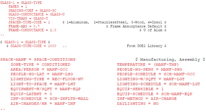
This sub-program reads the flexibly formatted data supplied by the user and translates that data into computer recognizable forms. In a stand-alone mode it also calculates response factors for the timedependent heat flow in thick walls and weighting factors for the thermal response of building spaces. The output of these calculations can be stored in a library for use in later simulations.

2) LOADS - the loads simulation. sub-program.
This sub-program calculates the sensible and latent components of the hourly heating or cooling load for each user-designated space in the building under the-following conditions. It is assumed that each space is kept at a constant temperature selected by the user and the sub-program does not take into account the outside air deliberately brought into the building for ventilation purposes. LOADS is responsive to weather and solar conditions, to schedules of people, lighting and equipment, to infiltration, to the time delay of heat transfer resulting from massive walls and roofs and to the effect of building shade on solar radiation. A variety of reports are available to the user including peak space and building loads by source and hourly data for a wide variety of variables.
3) SYSTEMS - the secondary HVAC simulation sub-program.
Loads produces what may best be described as a first approximation of the energy demands of a building. The function of SYSTEMS is to correct this approximation by taking into account the outside air requirements, the hours of operation of the equipment, the HVAC equipment control strategies and the transient response of the building when neither heating nor cooling is required to maintain the temperature and humidity set-points. Systems typically consist of conditioning and distributing air to the building. Conditioning the air is done with filters and steam, water and refrigerant coils. Systems also includes water conditioning and distribution to the building. The equipment associated with systems is referred to secondary equipment. The output of SYSTEMS is a list of zone and system peak and hourly loads actually required from each secondary HVAC system (the portion of the HVAC system that actually delivers conditioned air to the building spaces). It is these hourly rates that are passed on to the primary HVAC systems (that portion of the HVAC system that converts fuel to heat energy).
4) PLANT - the primary HVAC simulation sub-program
The PLANT sub-program simulates the behavior of boilers, turbines, chillers, cooling towers, solar collectors, etc., in delivering to the secondary systems the heat extraction and addition capabilities required. The equipment associated with plants is referred to as primary equipment. Taking into account the part-load characteristics (performance of the equipment under different demand requirements) of the primary equipment and the user-specified priorities for distribution of the tasks among the several components, PLANT calculates the fuel and electrical demands of the building aswell as the costs of these energy sources.
5) ECONOMICS - the economic analysis sub-program
This sub-program makes a life cycle cost analysis of different LOADS, SYSTEMS, and PLANT alternatives of interest to the user. It can be used to compare the costs of different building designs or to calculate savings to investment statistics for retrofits to an existing building.
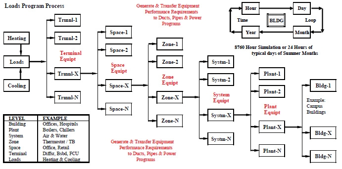
The figure below shows the structure of a building analysis program. There is an additional level called TERMINALS at the bottom and a level called BUILDING at the top. The terminal level links equipment in the various spaces that are connected by air distribution ductwork systems and fluid distribution piping systems. The building level looks at multiple plants in a building or in multiple buildings.


BUILDINGENVELOPE OPTIONS
- WallU-Value=0.07 RoofU-Value=0.05
- Glass Types: (a) SingleClear (b)DoubleClear (c)DoubleTint (d)DoubleLow-E
- DoubleClearGlazingPercent : (a) 70% (b) 60% (c) 50% (d) 40% (e) 30% (f) 20%(g) 10%
- 50%Glass +Daylighting+(b)DoubleClear (c)DoubleTint (d)DoubleLow-E
- 50%Solar Photo-Voltaic Panels on SouthExposure (50%DoubleLow-EGlass)
- Light Shelves (50%DoubleLow-EGlass)
- 24"ContinuousOverhangProjection, 12' aboveTop ofWindow
HVAC SYSTEMS OPTIONS
- Constant VolumeReheat+Electric PreHeat + ElectricBaseboard
0A. Like 0 except HotWaterHeating
- Central VAV, Inlet VaneControl + Elctrc PreHeat +VAVTerminl Box, 30%Min Set Point + ElctrcBaseboard
1A. Like 1 except Electric ZoneReheat instead ofBaseboard
- Like 1 except Variable FrequencyDrive +HWPreHeat +HWZoneHeat
- Like 2, AddAir andWater Side Economizers
- Like 3. AddAir toAirHeat Recovery (runaround coils at 40%efficiency)
- Like 4 except paralel flowFan Powered Terminal Boxes
- Like 5 except DeCentralized Floor by Floor Systems served byCentral CVOutdoor (OA)Air System
6A. Like 6 except Direct Outdoor Air per System
- PackagedACUnits (above ceiling) per Zone , Heat Reject to CondenserWater Loop, Central OASystem
- Packaged Terminal AC(through thewall) Units (Direct OA, Direct Heat Reject toOotdoors)
- Radiant Ceiling Panels on Perimeter (a) hot water heating (b) Chilledwater cooling + (c)OASystem
- Four-Pipe Fan Coil Units (CHWandHWCoils) +Central CVOutdoorAir Supply System
- Two-Pipe Fan Coil Units (CHWand Elec Coils) +Central CVOutdoorAir Supply System
- Two-Pipe Fan Coil Units (CHW-Summer& HW-Winter Changeover) +Central CVOutdoorAir Sup System
- Water SourceHeat Pumps +Central OASystem, Cooling TowerWater Loop, Supplemental ElectricHeat
- Water SourceHeat Pumps +Central OASystem, Ground SourceWater Loop, Supplemental ElectricHeat


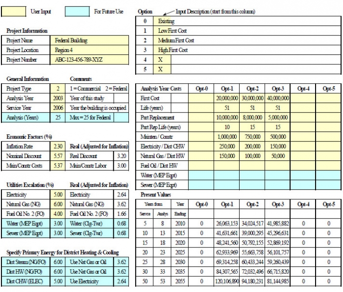
LifeCycleCostAnalysis (LCCA)

